Tissue ligating device
- Summary
- Abstract
- Description
- Claims
- Application Information
AI Technical Summary
Benefits of technology
Problems solved by technology
Method used
Image

Examples
first embodiment
[0073]the invention will be explained with reference to FIGS. 1 to 12B.
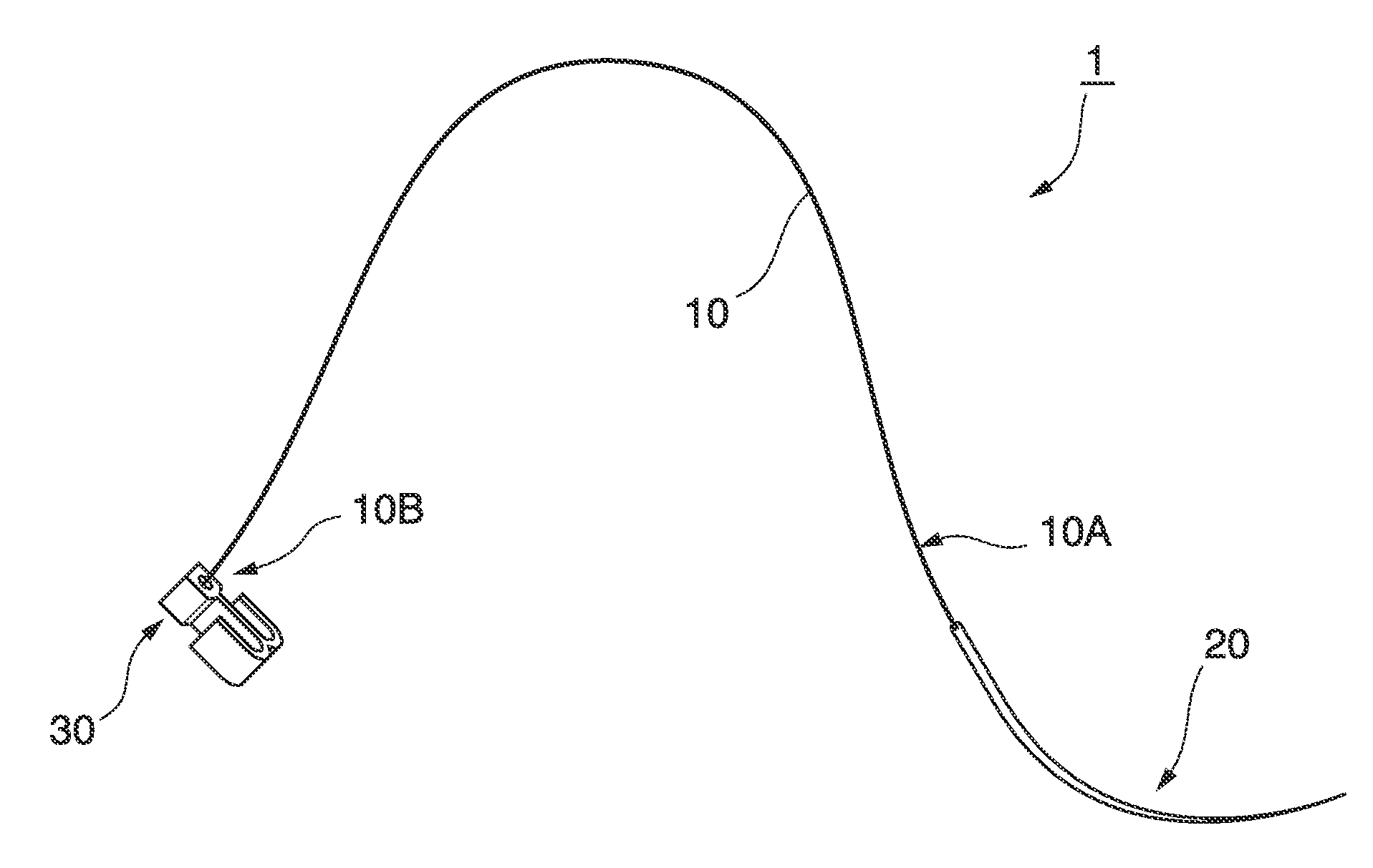
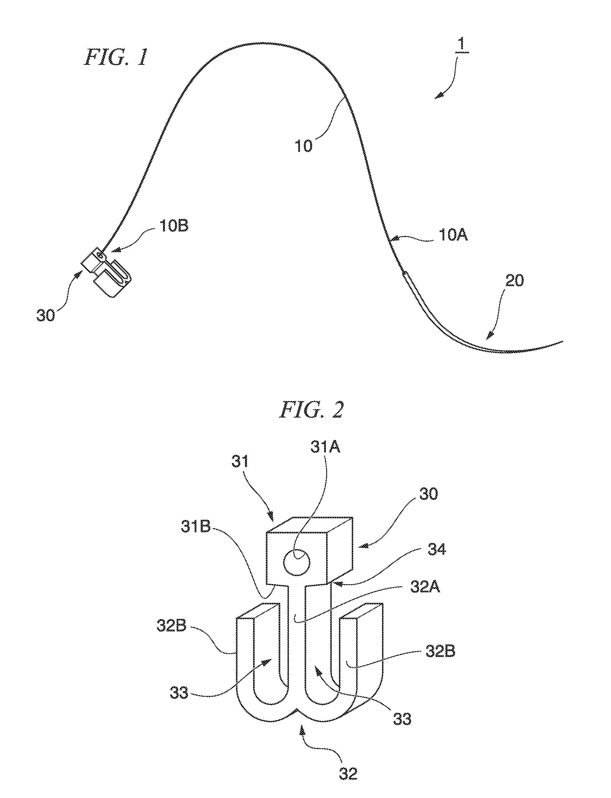
[0074]FIG. 1 is a view of a tissue ligating device (hereinafter referred as ligating device') 1 of this embodiment. The ligating device 1 includes a suture 10, a suture needle 20 attached to a first end 10A of the suture 10, and a suture fix member 30 attached to a second end 10B of the suture 10.
[0075]The suture 10 is preferably a member made of resin or metal that maintains a linear shape and has a certain degree of elasticity; however, a member without elasticity can also be used. For example, when the suture 10 is made of resin, it is preferably made of a bioabsorbable resin, since this has advantages such as eliminating the need for suture removal (in this case, the suture fix member is preferably also made of absorbable resin). However, the suture 10 can be made of a non-absorbable resin. As the suture 10, a monofilament member (single wire) or a multifilament member (plural wires) can be used depending on ...
second embodiment
[0110]Subsequently, the invention will be explained with reference to FIGS. 13 to 16F.
[0111]A ligating device 51 of this embodiment differs from the ligating device 1 described above in regard to the aspect of a suture fix part of the suture fix member. In the explanation below, constitutive elements that are common to those already described above are designated with like reference numerals and will not be repetitiously explained.
[0112]FIG. 13 is an enlarged view of a suture fix member 52 of the ligating device 51, and its vicinity. A single arm part 54 extends from a connection part 53. The arm part 54 extends while curving in a shape that is substantially oval in a front view of the suture fix member 52. A substantially oval housing part 55 is formed inside the curving arm part 54. The end of the curved arm part 54 extends towards the connection part 53, and forms a constriction part 54A that constricts an opening 55A in the substantially oval housing part 55 that the suture 10 p...
third embodiment
[0122]Subsequently, the invention will be explained with reference to FIGS. 17 to 19G. A ligating device 71 of this embodiment differs from those of the embodiments described above in regard to the shape of the housing part.
[0123]FIG. 17 is a perspective view of a suture fix member 72 of the ligating device 71, and its vicinity. In the suture fix member 72, a first arm part 74A and a second arm part 74B extending from a connection part 73 are formed so that they bend in a front view of the suture fix member 72. As a result, a housing part 75 formed between the first arm part 74A and the second arm part 74B is bent in a front view of the suture fix member 72.
[0124]In the embodiments of this invention, ‘bent’ denotes a state where a line connecting a deepest part of the housing part, where the distance in alignment with form of the housing part from an opening in the housing part through which the suture enters is greatest, to the opening cannot be drawn so that, when viewed from at l...
PUM
 Abstract
Description
Claims
Application Information
 - Generate Ideas
- Intellectual Property
- Life Sciences
- Materials
- Tech Scout
- Unparalleled Data Quality
- Higher Quality Content
- 60% Fewer Hallucinations
Browse by: Latest US Patents, China's latest patents, Technical Efficacy Thesaurus, Application Domain, Technology Topic, Popular Technical Reports.
© 2025 PatSnap. All rights reserved.Legal|Privacy policy|Modern Slavery Act Transparency Statement|Sitemap|About US| Contact US: help@patsnap.com