
Box end ratchet wrench with reduced ratcheting arc

a ratcheting arc and wrench technology, applied in the field of box end ratchet wrenches and ratchet drive wrenches, can solve the problems of limited to a “nominal ratcheting arc”, wrenches require a large rotational degree in order to use the wrench, and the wrenches cannot be used in confined spaces, so as to achieve the effect of reducing the ratcheting ar

Active Publication Date: 2012-07-05
GAPP STEVEN JAMES +2
View PDF14 Cites 8 Cited by
  • Summary
  • Abstract
  • Description
  • Claims
  • Application Information

AI Technical Summary

Benefits of technology

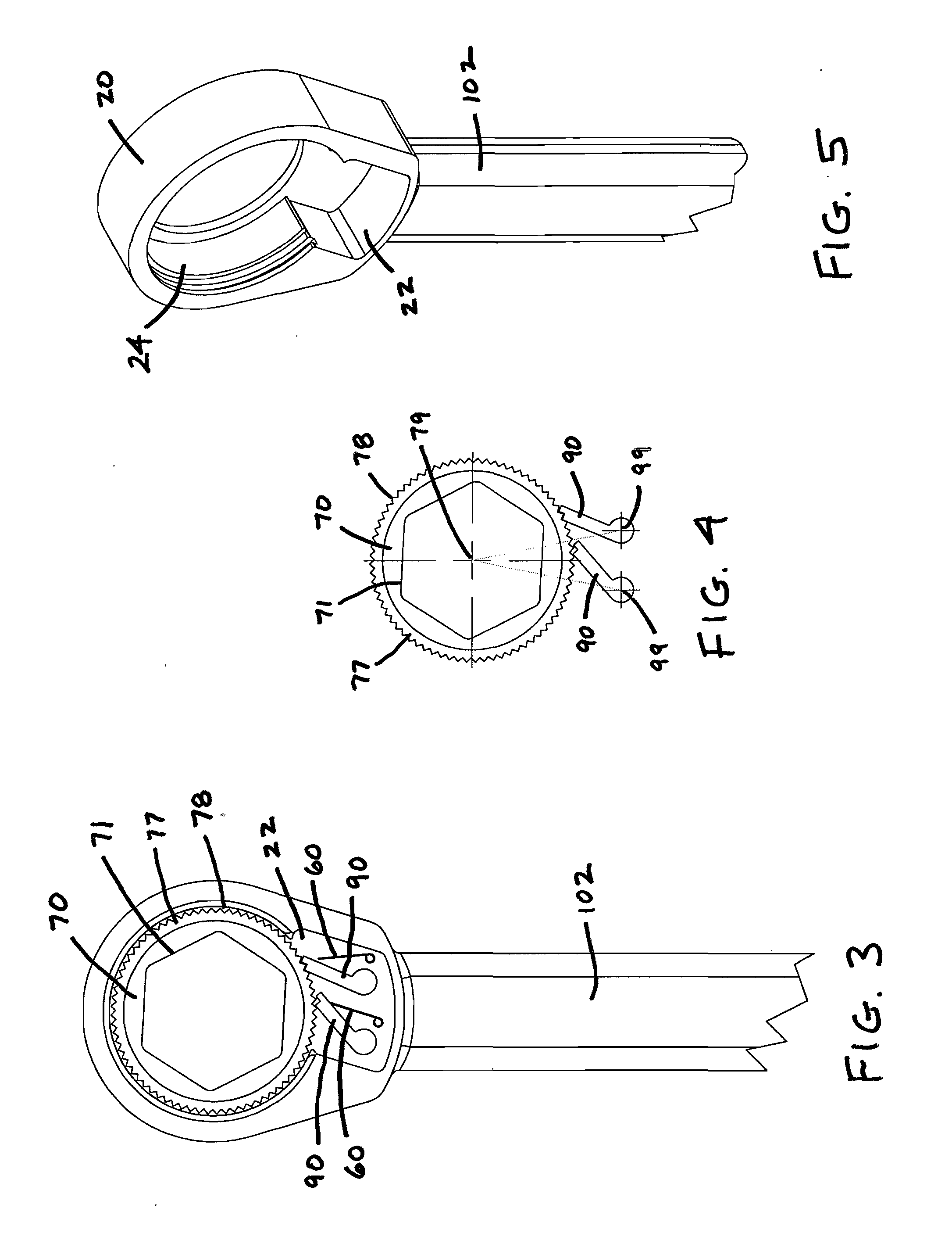
[0010]This configuration allows smaller wrench rotation (or “ratcheting arc”) of down to 2.5, 1.75, or lower, degrees required to apply torque. The present invention further allows for a multiple pawl assembly. In the view of these inventors, a multiple pawl assembly is advantageous because it overcomes the geometrically defined restriction of the number of teeth on a ratcheting gear wheel as a limitation to achieving a reduced ratcheting arc. The advantage is achieved insofar as alternately or successively engaged pawls do not require the gear wheel to travel the complete increment of one gear tooth to engage the gear. Prior art limits the nominal ratcheting arc by dividing the number of teeth on the gear into 360. For example, with a gear having 72 teeth, the nominal ratcheting arc results in a 5 degree ratcheting arc (i.e. 360 degrees+72 teeth=5 degrees per tooth).

Problems solved by technology

If the ratchet wheel is rotated in a “backward” direction, however, the pawl will only allow movement until it comes in contact with the opposite side of the next tooth back and it will jam there.
One problem generally known in the art of box type wrenches using ratchet and pawl systems is that they are limited to a “nominal ratcheting arc,” which is defined by the number of teeth on the ratchet gear divided into 360 degrees.
However, these wrenches require a large rotational degree in order to use the wrench which is not possible in confined spaces.
The need for such a large rotational movement lessens the utility of such wrenches.
If a large degree of motion is required to rotate the ratchet, the wrench cannot be used in small or tight spaces.

Method used


Image

  • Box end ratchet wrench with reduced ratcheting arc
  • Box end ratchet wrench with reduced ratcheting arc
  • Box end ratchet wrench with reduced ratcheting arc

Examples


Embodiment Construction

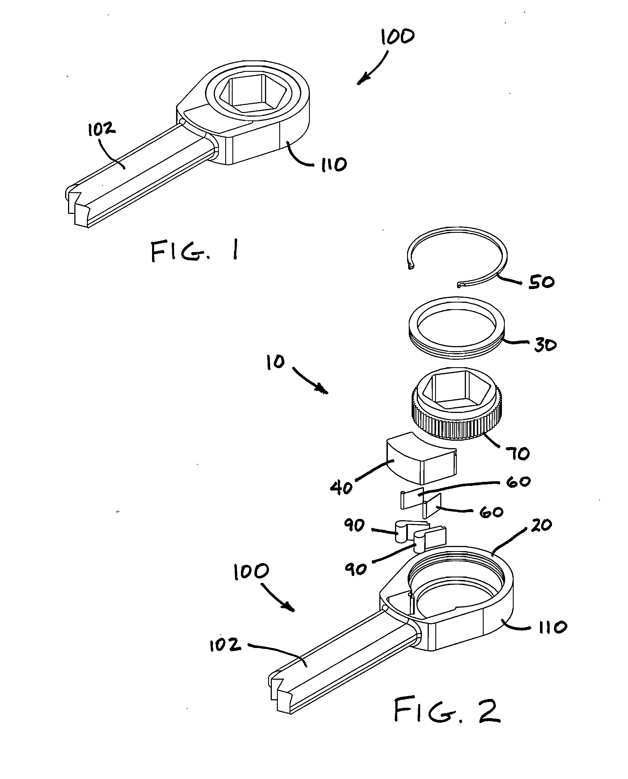
[0034]Referring now to the drawings in detail, wherein like numbered elements refer to like elements throughout, FIG. 1 illustrates a perspective view of an exemplary embodiment of a box ended ratchet wrench, generally identified 100, that is constructed in accordance with the present invention. The box ended ratchet wrench 100 may be used to apply torque force in a clockwise or counter-clockwise direction. In the embodiment shown, box ended ratchet wrench 100 comprises an ergonomic handle 102 and a box ended wrench head, generally identified 110. The box ended wrench head 110 comprises a ratchet wrench head assembly, generally identified 10.

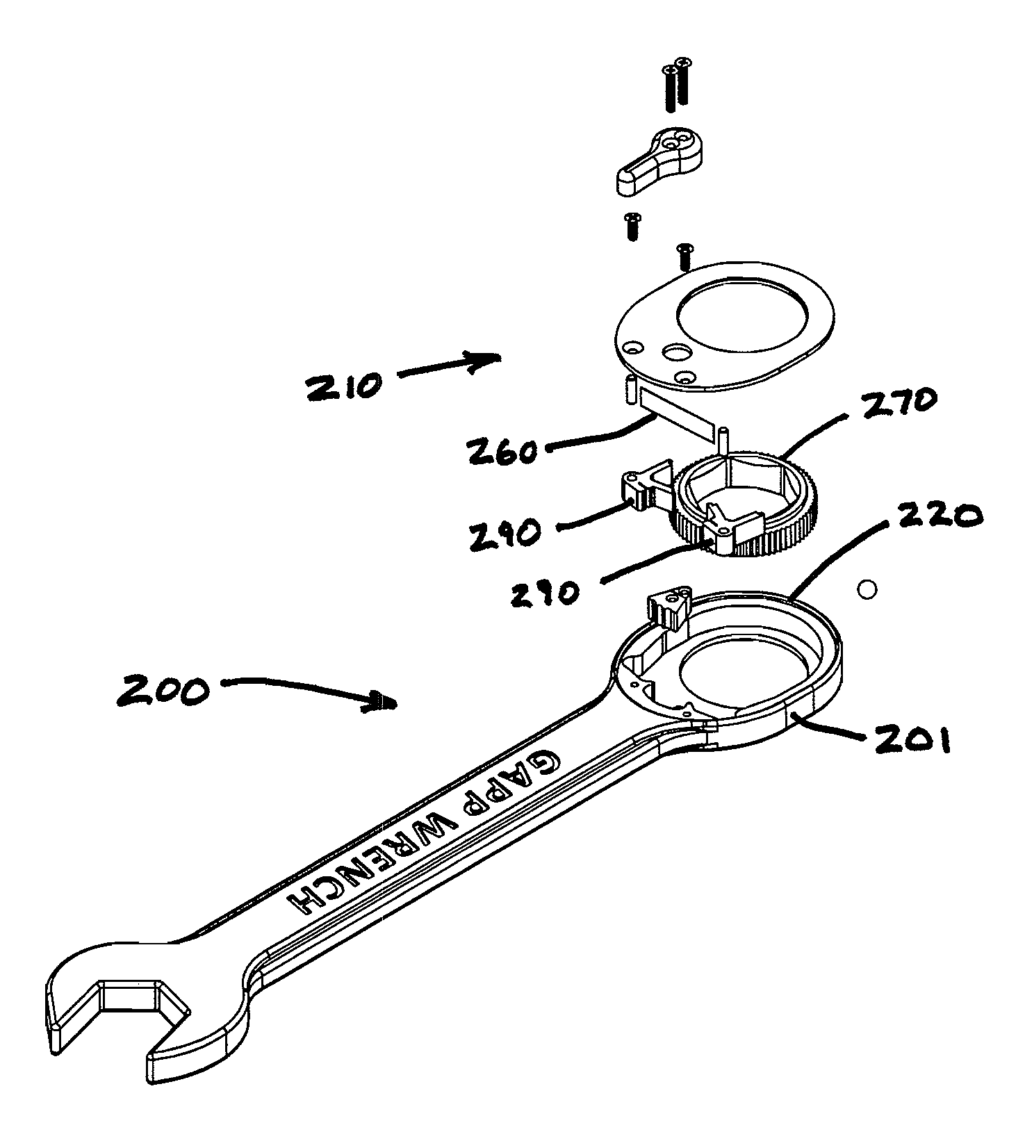
[0035]Referring now to FIG. 2, it shows an exploded view of the various components used in the ratchet wrench head assembly 10 of the box ended ratchet wrench head 110 of the present invention. In the exemplary embodiment that is illustrated, the box ended ratchet wrench head assembly 10 comprises a wrench head body (or housing) 20, a body inser...


PUM


Abstract

A reduced arc box end ratchet wrench or ratchet drive wrench utilizes a multiple pawl ratchet assembly comprised of a body having an insert cavity to enclose critical components of an insert that is secured within the ratchet assembly. The insert is set into the wrench body and includes a plurality of pivoting pawls. Each pawl comprises a lever arm with ratchet engaging teeth. The pawl arms are positioned relative to the ratchet wheel to create “pawl swing arcs” and “reduced ratcheting arcs” to alternately or successively engage a portion of the teeth of a ratchet wheel at all times. This configuration allows smaller degrees between ratchet teeth and a smaller wrench rotation that is otherwise required to apply torque.

Description

[0001]This application is a continuation-in-part of U.S. patent application Ser. No. 13 / 300,494 filed Nov. 18, 2011; which is a continuation-in-part of U.S. patent application Ser. No. 12 / 419,791 filed Apr. 7, 2009, now abandoned. The subject matter of these applications is incorporated herein by reference.FIELD OF THE INVENTION[0002]The present invention relates generally to the field of box end ratchet wrenches and ratchet drive wrenches. More specifically, it relates to a box end ratchet wrench and / or a ratchet drive wrench with a multi-pawl assembly that facilitates a reduced ratcheting arc of 5 degrees, 2.5 degrees, 1.75 degrees, or lower.BACKGROUND OF THE INVENTION[0003]A ratchet wrench is a type of wrench having at least one end that surrounds a nut or the head of a bolt. The wrench provides a mechanical advantage by applying torque to turn bolts, nuts or other items designed to interface with a wrench. The ratcheting mechanism allows the nut or bolt to be tightened or loosen...

Claims


Application Information

Patent Timeline
Patent Type & Authority Applications(United States)
IPC IPC(8): B25B13/46
CPCB25B13/08B25B13/48B25B13/463B25B13/462B25B13/467
Inventor GAPP, STEVEN JAMESJOHNSON, CLINTON M.FELTON, J. REED
Owner GAPP STEVEN JAMES
Learn More