Screw holding device and screwdriver

a screw and holding device technology, applied in the direction of screwdrivers, power-driven tools, wrenches, etc., can solve the problems of consuming a lot of physical strength of workers, the rotation speed of hand tools is very low, and the tool cannot provide an additional torque, etc., to achieve the effect of more compact volume and rotation speed

Inactive Publication Date: 2016-02-04
POSITEC POWER TOOLS (SUZHOU) CO LTD
View PDF7 Cites 6 Cited by
  • Summary
  • Abstract
  • Description
  • Claims
  • Application Information

AI Technical Summary

Benefits of technology

[0031]Compared with the prior art, beneficial effects of the present invention are as follows: in the process that the clamping arms of the screw holding device rotates from the clamp position to the release position, the clamp arms need to rotate a smaller angle, the rotation speed of the clamping arms are faster within the same stroke of movement, and by use of rapid rotation, the volume of the screw holding device is more compact, which adapts to more types of screwdrivers.

Problems solved by technology

However, such a method has many shortcomings, and the hand tool cannot provide an additional torque and can only rely on workers to provide a torque by themselves, which will consume lots of physical strength of the workers.
In addition, the rotation speed of the hand tool is very low, so that the time it takes to drive the screw into the workpiece is greatly extended, which reduces the workers' efficiency.
However, in the process of driving the screw, it is very easy to deviate from the normal direction, and the workers have to manually centralize the screw to drive the screw.
This brings about great inconvenience to the workers.
For example, U.S. Pat. No. 8,047,100B2 discloses a screw support device, but such a screw support device has a telescoping leg which is provided thereon with a magnetic structure and can adsorb and support a screw; however, such a device cannot support the screw stably, and at the time of work, the screw is highly susceptible to shake, which results in that the screw cannot be precisely driven into the workpiece.
However, the screw clamping device has a greater volume and has a smaller clamping force for the screw, and the screw is very easy to fall off from the clamping device or a situation where the screw tilts occurs, which brings about inconvenience to the driving process and cannot really improve the work efficiency.

Method used


Image

  • Screw holding device and screwdriver
  • Screw holding device and screwdriver
  • Screw holding device and screwdriver

Examples


Embodiment Construction

[0047]Preferred embodiments of the present invention are elaborated below with reference to the accompanying drawings, to enable advantages and features of the present invention to be understood by those skilled in the art more easily, thus making clearer definition to the protection scope of the present invention.

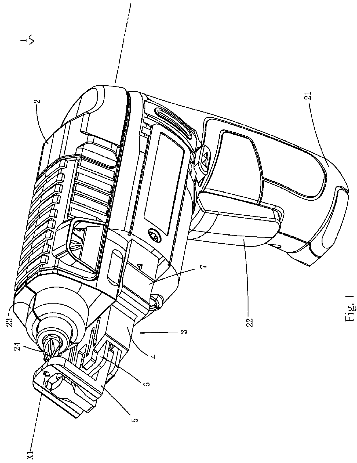
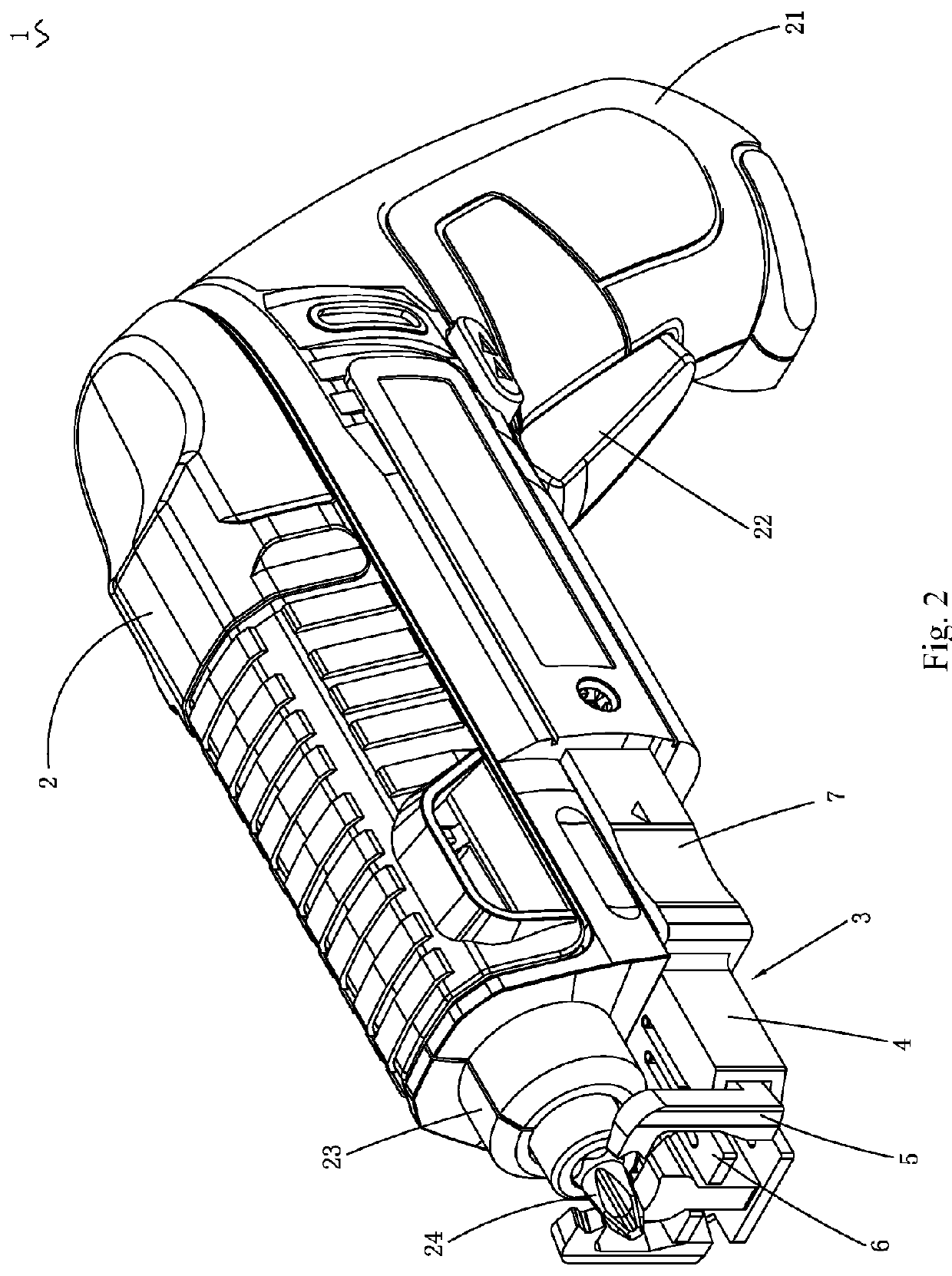
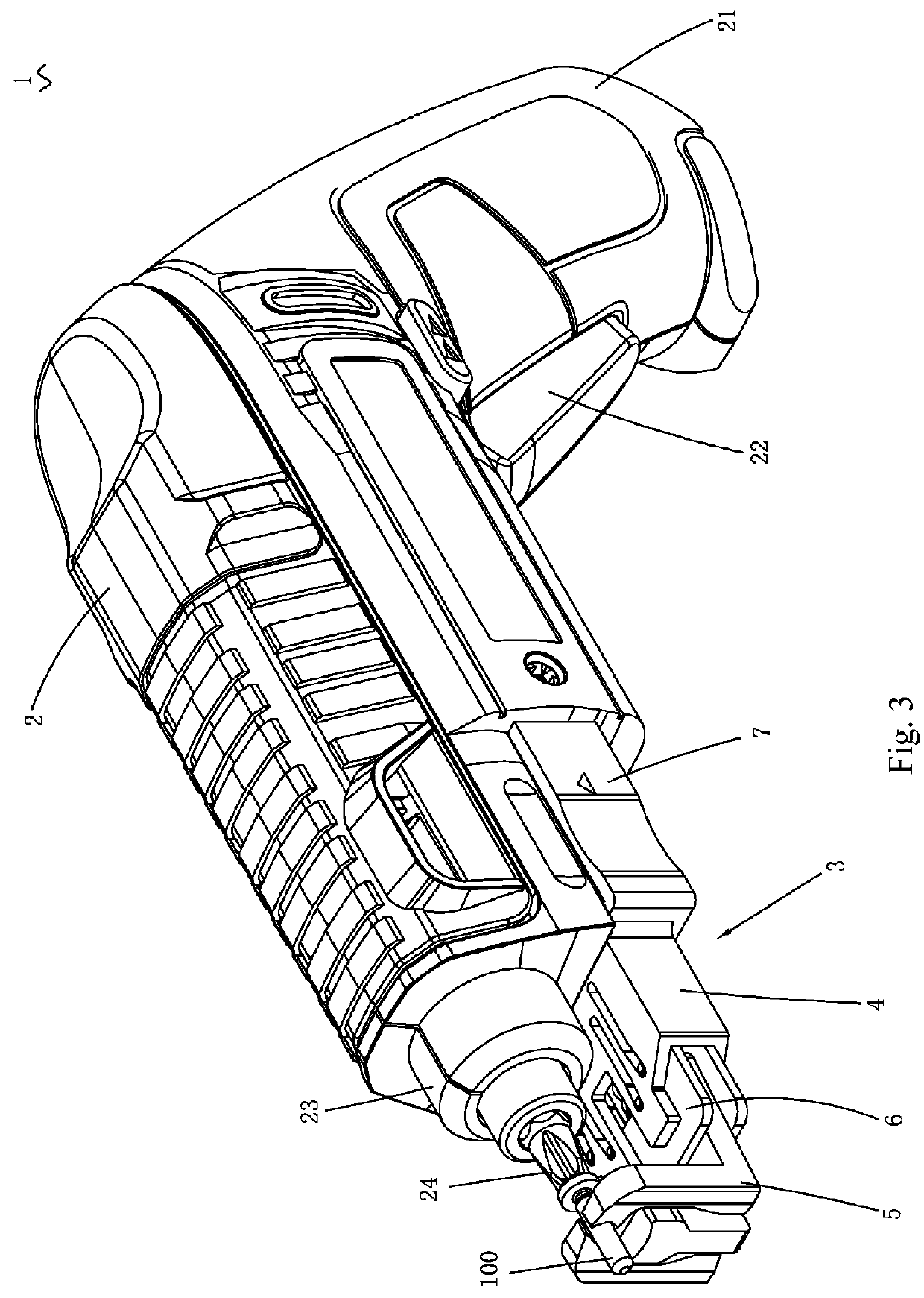
[0048]FIG. 1 to FIG. 8 show a screwdriver 1 according to one embodiment of the present invention. The screwdriver herein may be a screwdriver that belongs to an electric tool and may also be a hand tool. In this embodiment, the screwdriver 1 includes a housing 2. The housing 2 substantially extends along a direction of a work axis X1. The housing 2 contains a motor (not shown) therein. The motor is used to produce rotary output about the work axis X1. The screwdriver further includes a handle 21 for holding. The handle 21 extends along a direction deviating from the axis, so that the screwdriver 1 is pistol-shaped wholly. The handle 21 is provided thereon with a switch 22 ...


PUM


Abstract

A screw holding device configured to assist a screwdriver in holding a screw, the screwdriver providing rotary power output to the screw, the screw holding device comprising: a body capable of being connected with the screwdriver; a holder connected with the body and comprising at least two clamping arms configured to move between a clamp position wherein the screw is clamped and a release position wherein the screw is released; and a driving mechanism configured to drive the clamping arms and comprising a guide unit and a connection unit. The connection unit is in correspondence to the clamping arms and comprises first and second connectors respectively connected with the clamping arms. The guide unit drives the first connector to move longitudinally and laterally, and drives the second connector to move at least longitudinally, so as to drive the clamping arms to produce pivotal motion and longitudinal linear motion.

Description

CROSS-REFERENCE TO RELATED APPLICATION[0001]This application is a continuation of International Patent Application No. PCT / CN2014 / 075469, filed on Apr. 16, 2014, which in-turn claims priority to Chinese Patent No. 201310131642.0, filed on Apr. 16, 2013, the contents of which are incorporated herein by reference.BACKGROUND[0002]1. Technical Field[0003]The present invention relates to a screw holding device and a screwdriver.[0004]2. Related Art[0005]In people's daily life, tightening the screws is very common and can be applied to many occasions. At present, there are several common methods of driving a screw into a workpiece, and one way is to drive the screw into the workpiece by using a hand tool, in which the hand tool may be a slot-type screwdriver, a Philip's type screwdriver or the like. However, such a method has many shortcomings, and the hand tool cannot provide an additional torque and can only rely on workers to provide a torque by themselves, which will consume lots of p...

Claims


Application Information

Patent Timeline
Patent Type & Authority Applications(United States)
IPC IPC(8): B25B23/10B25B21/00B25B23/00
CPCB25B23/10B25B21/00B25B23/005
Inventor MA, YICHUNXU, JINGTAOZHANG, SHISONG
Owner POSITEC POWER TOOLS (SUZHOU) CO LTD
Why Eureka
Try Eureka