Multi-stage radial flow turbine

a radial flow turbine and multi-stage technology, applied in machines/engines, renewable energy generation, greenhouse gas reduction, etc., can solve the problems of limited conventional axial flow designs, and achieve the effect of increasing efficiency and less efficien

Active Publication Date: 2018-01-02
FRENCH JOHN
View PDF11 Cites 9 Cited by
  • Summary
  • Abstract
  • Description
  • Claims
  • Application Information

AI Technical Summary

Benefits of technology

[0007]The present invention is directed to a multi-stage radial turbine for usage in energy capture from fluid streams with low to moderate relative speed. The primary sources of low energy content streams include wind and gravitational flow of water; however, other energy sources can be used. Additionally, the turbine can be driven and utilized as a liquid pump, gaseous phase fan, or gaseous phase compressor. The efficiency of the turbine allows it to be incorporated into many different devices such as, but not limited to, non-stationary land-based vehicles and waterborne vessels. When the turbine is used for land-based vehicles or other types of non-stationary devices, the velocity differential between the device and the surrounding fluid can create the motive force necessary to drive the turbine; however, this is not required. The resulting shaft work produced by the turbine can be used to drive generators and / or other types of rotating equipment. The design and mechanism by which the turbine is driven is novel to the art. Traditionally, air or a liquid was directed perpendicular to the axis of rotation of the turbine blade. For example, traditional wind turbines that are used to generate electricity are designed to have the blades rotated while the blades face into the wind. Similarly, turbine generators for use in the generation of hydroelectric energy are designed such that water is directed into the face of the blades or is passed out the outer edge of the blades. Although these designs have been traditionally used to generate electricity, such designs have been found to be much less efficient than the design of the present invention. It has been found that by directing at least a majority (e.g., 51%, 51.01%, 51.02% . . . 99.98%, 99.99%, 100% and any value or range therebetween) of fluid (gas and / or liquid) toward the vanes of the blade in a plane that is ±50° perpendicular (e.g., ±30°, ±20°, ±10°, etc.) to the axis of rotation of the blade and from a direction from an interior region to an exterior region of the blade (e.g. radially outward), significantly increased efficiencies can be achieved.
[0008]In another non-limiting application of the present invention, the combination achieved by combining a radial compressor, a burner and a radial energy capturing turbine can be used to create a radial internal combustion engine that is analogous to a multi-staged, axial flow turbine engine. One non-limiting advantage of the radial design is that it can operate efficiently in flow conditions that are much slower and / or have rotational speeds that are greatly reduced than the necessary minimum speeds for axial designs. These slower flows are actually most commonly encountered. For example, stationary fans typically are used to accelerate air that begins at near stagnant velocity.
[0014]The new radial design turbine / collector combination of the present invention is believed to result in improved performance and which exceeds the axial flow performance by an order of magnitude or greater of prior devices. This huge performance difference can be observed using the provided graph (FIG. 1) and by simply visually extending the axial flow efficiency curve far to the left to where is located the very low relative speed of operation. As is evident from FIG. 1, the novel design of the present invention can obtain efficiency values that were heretofore unachievable at fluid speeds.

Problems solved by technology

The conventional axial flow designs are limited by the amount of energy contained in the fluid stream.

Method used


Image

  • Multi-stage radial flow turbine
  • Multi-stage radial flow turbine
  • Multi-stage radial flow turbine

Examples


Embodiment Construction

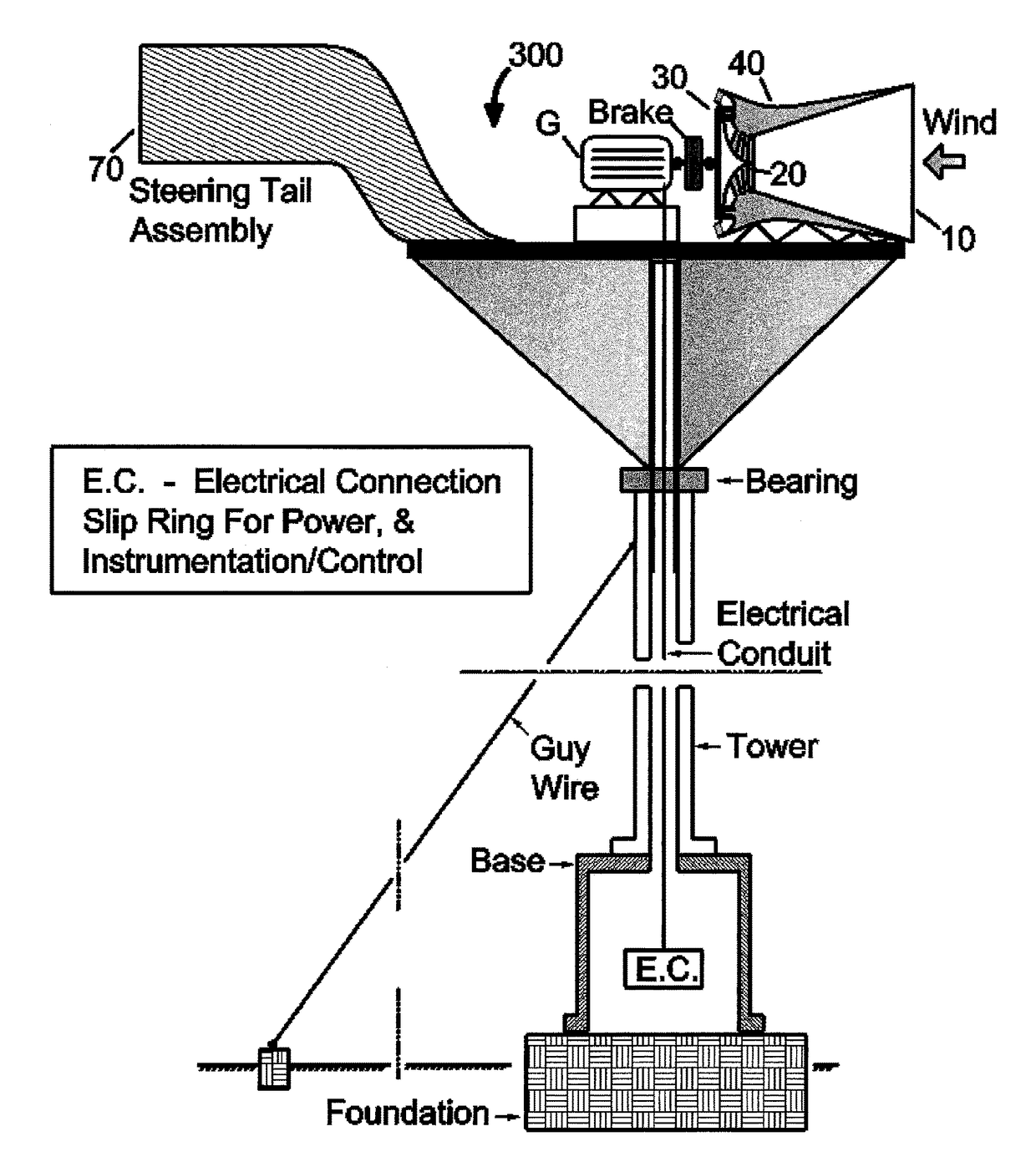
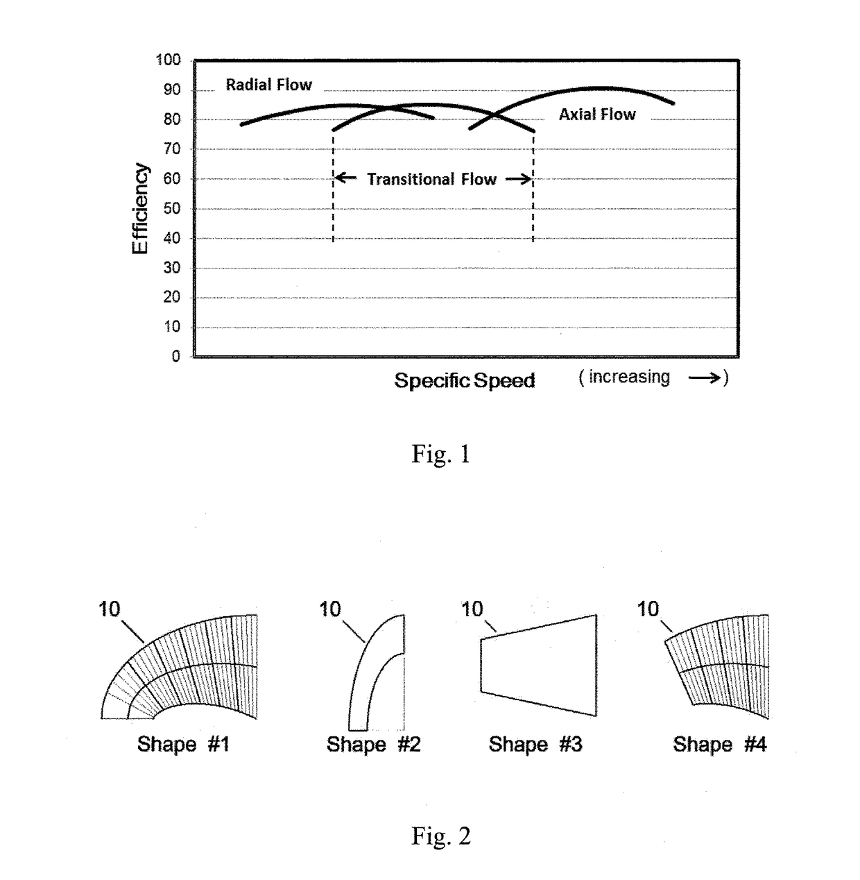
[0047]Referring now in greater detail to the drawings, wherein the showings are for the purpose of illustrating various embodiments of the invention only, and not for the purpose of limiting the invention, the present invention is directed to a multi-stage radial turbine for usage in energy capture from fluid streams with low to moderate relative speed. One non-limiting advantage of the radial design is that it can operate efficiently in flow conditions that are much slower and / or have rotational speeds that are greatly reduced than the necessary minimum speeds for axial designs. Additional discussion and quantification of expected performance gains by controlling secondary flows are set forth in more detail below.

Power from Wind

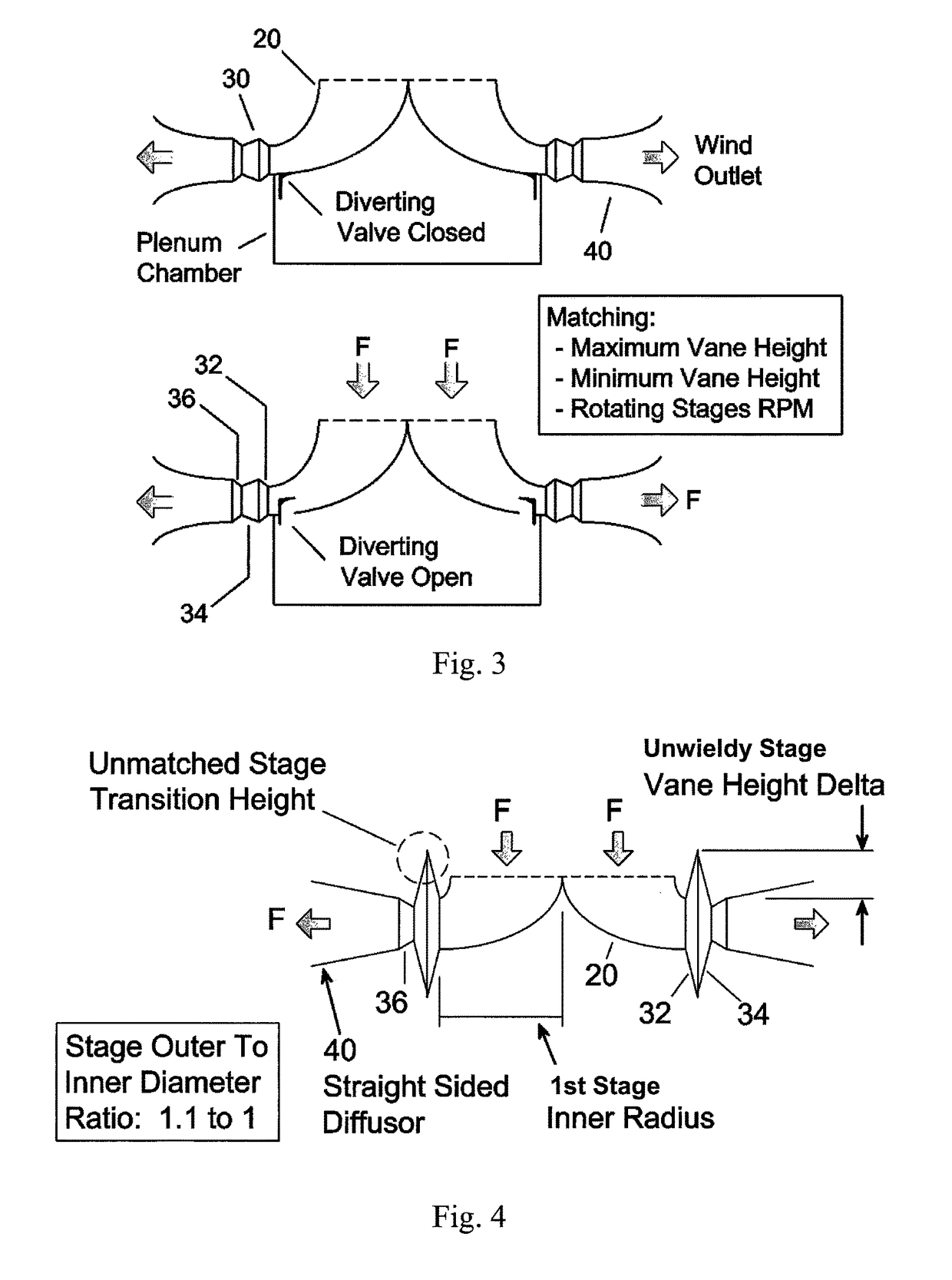
[0048]In one non-limiting aspect of the present invention, the invention is directed to a radial design having improved performance for producing electrical power from wind-driven devices. Several of the design aspects of the wind-driven turbine have a direc...


PUM


Abstract

A multi-stage radial turbine for usage in energy capture from fluid streams with low to moderate relative speed.

Description

[0001]The present invention claims priority on U.S. Provisional Patent Application Ser. No. 61 / 782,044 filed Mar. 14, 2013, which is incorporated herein by reference.[0002]The present invention is directed to a multi-stage radial turbine for usage in energy capture from fluid streams with low to moderate relative speed. Additionally, the turbine can be used as a liquid pump, gaseous phase fan or compressor.BACKGROUND OF THE INVENTION[0003]Various radial designs for a turbine have been utilized since the dawn of the industrial revolution and their characteristic flow is found in numerous patents. The following qualitative graph is slightly modified from that found in “Mechanics of Fluids”; author: Irving Shames; ISBN 0-07-056385-3, page 616.[0004]The graph illustrated in FIG. 1 shows through curves of efficiency versus relative velocity whether the optimal flow regime is either radial, axial or the transitional range between these two. At low speeds, the radial orientation provides s...

Claims


Application Information

Patent Timeline
Patent Type & Authority Patents(United States)
IPC IPC(8): F03D3/04F03D3/00F03D3/02F03D13/20F03D9/00F03B3/00F03D9/30
CPCF03D3/0427F03B3/00F03D3/005F03D3/02F03D9/00F03D13/20Y02E10/74F05B2210/16F05B2240/93F05B2240/941Y02E10/223Y02E10/727B60K16/00F03D3/0454F03D3/0463Y02E10/20Y02E10/72F03D1/04F03D9/20F03D9/32
Inventor FRENCH, JOHN
Owner FRENCH JOHN
Why Eureka
Try Eureka