Flaked ice maker

a technology of ice maker and flake, which is applied in the field of improved flaked ice maker, can solve the problems of increasing the difficulty of acquiring ice, posing a danger, and requiring both labor and time, and achieves the effects of less labor and time, convenient maintenance, and convenient installation

Active Publication Date: 2006-02-28
EBAC
View PDF10 Cites 33 Cited by
  • Summary
  • Abstract
  • Description
  • Claims
  • Application Information

AI Technical Summary

Benefits of technology

[0019]The present invention provides an ice maker having an extruder that is capable of depositing ice in a storage bin above it. The present invention also allows the size of the ice flakes to be adjusted to any desired size. The design prevents cleaning chemicals from leaking into the ice bin and prevents chlorine gas from entering the ice maker. It also allows for easier installation as the ice maker may be located on the ground. It avoids the need for earthquake proof equipment and eliminates the danger of having a heavy object several feet above the ground.
[0020]The improved flaked ice maker of the present invention has a sleeve and an ice transport tube located directly above the extrusion head. Just inside the sleeve is an adjustable, beveled surface which breaks the ice into pieces of a predetermined size. The flaked ice is pushed up the ice transport tube by new flaked ice entering into it below it. Because the ice is relatively loose, it does not c

Problems solved by technology

Persons retrieving ice from the bin must then bend over and this increases the difficulty of acquiring ice.
Because ice makers are very heavy, this poses a danger.
Those skilled in the art will appreciate that it is both difficult and expensive to securely attach an ice maker to a wall.
Ice makers that are relatively far above the ground are also difficult to maintain and repair.
The danger is usually worsened by the fact that ice makers are typically in high volume traffic areas.
When ice machines are not properly maintained, they may freeze up.
This may cause an ice machine to shake or shutter violently.
If the ice m

Method used


Image

  • Flaked ice maker
  • Flaked ice maker
  • Flaked ice maker

Examples


Embodiment Construction

[0026]The embodiments discussed herein are merely illustrative of specific manners in which to make and use the invention and are not to be interpreted as limiting the scope of the instant invention.

[0027]While the invention has been described with a certain degree of particularity, it is to be noted that many modifications may be made in the details of the invention's construction and the arrangement of its components without departing from the spirit and scope of this disclosure. It is understood that the invention is not limited to the embodiments set forth herein for purposes of exemplification.

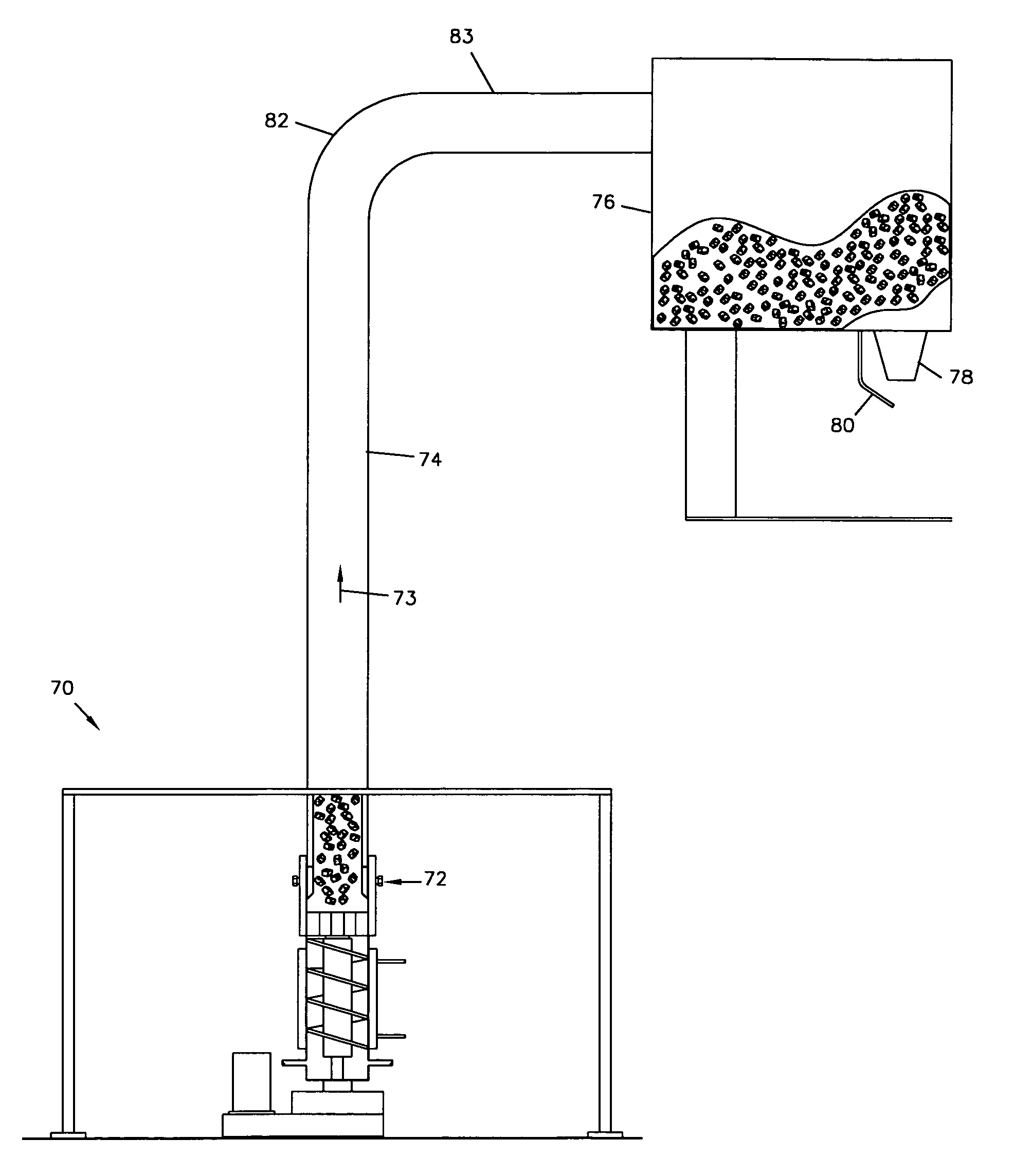
[0028]The present invention comprises an ice transport tube for transporting flaked ice from an extrusion head to a bin above it. It is adjustable so that the size of the flaked ice pieces may be adjusted but has no moving parts. It may be fitted to any existing screw-type flaked ice machine. It may be used to deposit ice in a single bin or multiple bins.

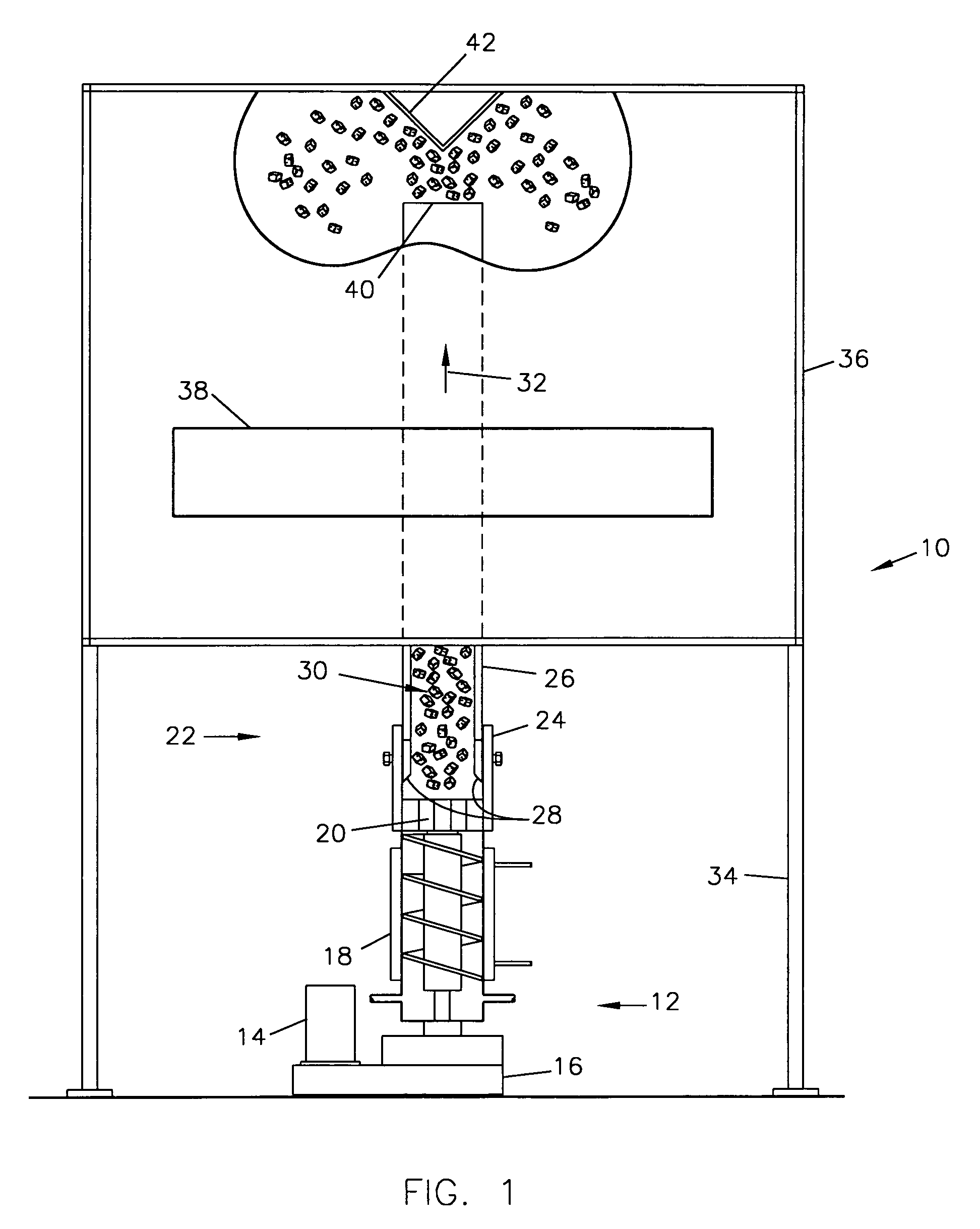
[0029]FIG. 1 shows a preferred emb...


PUM


Abstract

An apparatus and method for transporting flaked ice upward. The device includes an upward transport tube with a shortened sleeve. A beveled lower end of the transport tube forms flaked ice of a desired size and transports it upward. The size of the flaked ice formed may be changed.

Description

BACKGROUND OF THE INVENTION[0001]1. Field of the Invention.[0002]The present invention relates to an improved flaked ice maker capable of depositing ice into bins that are substantially above the ice maker. Specifically, the present invention provides a flaked ice maker that pushes flaked ice upward through a tube without the need for an auger.[0003]2. Prior Art.[0004]There are many existing types of flaked ice making machines. Generally, when flaked ice is made by a screw-type machine, as it breaks into ice flakes, it falls to the side and downwardly from the machine. The extruding head breaks the ice into flakes in a radially outward direction. Often an ice sweep brushes the pieces of flaked ice to one side where they may fall down a chute or directly into a bin. Several different designs have been developed.[0005]U.S. Pat. No. 4,429,551, issued on Feb. 7, 1984 to Hizume discloses an extrusion head for an auger type ice maker whose bosses extend downward over the topmost portion o...

Claims


Application Information

Patent Timeline
IPC IPC(8): F25C1/14
CPCF25C1/147F25C5/002F25C5/20F25C5/142
Inventor BROOKS, CHARLES A.
Owner EBAC
Why Eureka
Try Eureka