Automatic transmission control device

a transmission control device and automatic transmission technology, applied in mechanical instruments, digital data processing details, instruments, etc., can solve the problems of increasing the size and cost of the automatic transmission control device, increasing the number of parts, and increasing the size of the line pressure control valve, so as to reduce the time shorten the time period for filling the clutch chamber with working fluid, and increase the fluid pressure to be applied to the friction elements.

Inactive Publication Date: 2008-09-18
DENSO CORP
View PDF3 Cites 9 Cited by
  • Summary
  • Abstract
  • Description
  • Claims
  • Application Information

AI Technical Summary

Benefits of technology

[0019]According to a further feature of the present invention, an electronic control device controls the electromagnetic control device, such that the output pressure of the electromagnetic control device is temporally increased when starting a transmission gear change. When the electronic control device controls to temporally increase the output pressure of the electromagnetic control device, the maximum pressure selected among the output pressures of the electromagnetic control devices is also rapidly increased, and the discharge amount of the pump is correspondingly increased in accordance with the increase of the maximum pressure. Accordingly, the fluid pressure to be applied to the friction elements can be rapidly increased at proper timing during a period of transmission gear change operation, in particular during an initial period of the gear change operation in which clutches are brought into engagement by filling a clutch chamber thereof with the working fluid. Namely, a time period for filling the clutch chamber with the working fluid can be shortened.
[0020]According to a further feature of the present invention, the electronic control device also controls the electromagnetic control device such that the output pressure of the electromagnetic control device is temporally increased when starting engagement of a lock-up clutch. Accordingly, the lock-up clutch can be rapidly engaged as in the same manner to the friction elements.
[0021]According to a still further feature of the present invention, the electronic control device controls the electromagnetic control device such that the output pressure thereof is increased, when temperature of the working fluid becomes lower than a predetermined value. Therefore, even when viscosity of the working fluid is high due to a low temperature, the fluid pressure to be applied to the friction elements can be smoothly increased.
[0022]According to a still further feature of the present invention, the electronic control device controls the electromagnetic control device such that the output pressure thereof is increased, when rotational number of an internal combustion engine is lower than a predetermined value. The discharge amount of the pump is reduced when the rotational speed of the engine becomes lower. However, according to such an arrangement, even when the rotational speed of the engine becomes lower, the fluid pressure to be applied to the friction elements can be smoothly increased.
[0023]According to a still further feature of the present invention, an operational speed of the capacity varying device, which changes the discharge amount of the pump, is decreased so that a rapid change of the discharge amount of the pump can be prevented.
[0024]According to a still further feature of the present invention, a relief valve is provided in a pump discharge line, into which the pump discharges the pressurized working fluid. The relief valve is operated (opened) when the discharge pressure of the pump exceeds a predetermined value, so that the fluid pressure in the pump discharge line may not become higher than such predetermined value. As a result, damages at parts and components for the hydraulic circuit can be prevented.

Problems solved by technology

Accordingly, a number of parts is increased, and size and cost for the automatic transmission control device are increased.
However, according to such a structure, as disclosed in the above JP 2005-127435, in which the line pressure control valve is used to generate the line pressure in accordance with the command pressure by adjusting a discharge amount of working fluid discharged from a pump, the line pressure control valve may become larger in size, because the discharge amount of the pump becomes larger as an engine rotational speed is increased and the line pressure control valve has to cope with such large amount of the working fluid from the pump.
Furthermore, such large amount of the working fluid is supplied into the line pressure control valve, a cross-sectional area of a passage for connecting the pump to the line pressure control valve becomes larger.
Therefore, the discharge amount of the pump may come short or may be overproduced with respect to a demanded flow amount of the automatic transmission, in a certain range of the engine rotational speed.
As a result, an appropriate oil pressure may not be applied to the friction elements at necessary timings required by the automatic transmission.
Accordingly, a number of parts is increased to increase manufacturing cost.
Furthermore, an appropriate amount of the working oil may not be supplied to the automatic transmission at appropriate timings, even when the eccentric amount of the pump is controlled.
As above, it is a problem that an appropriate pressure may not be applied to the automatic transmission at the necessary timings.

Method used


Image

  • Automatic transmission control device
  • Automatic transmission control device
  • Automatic transmission control device

Examples


first embodiment

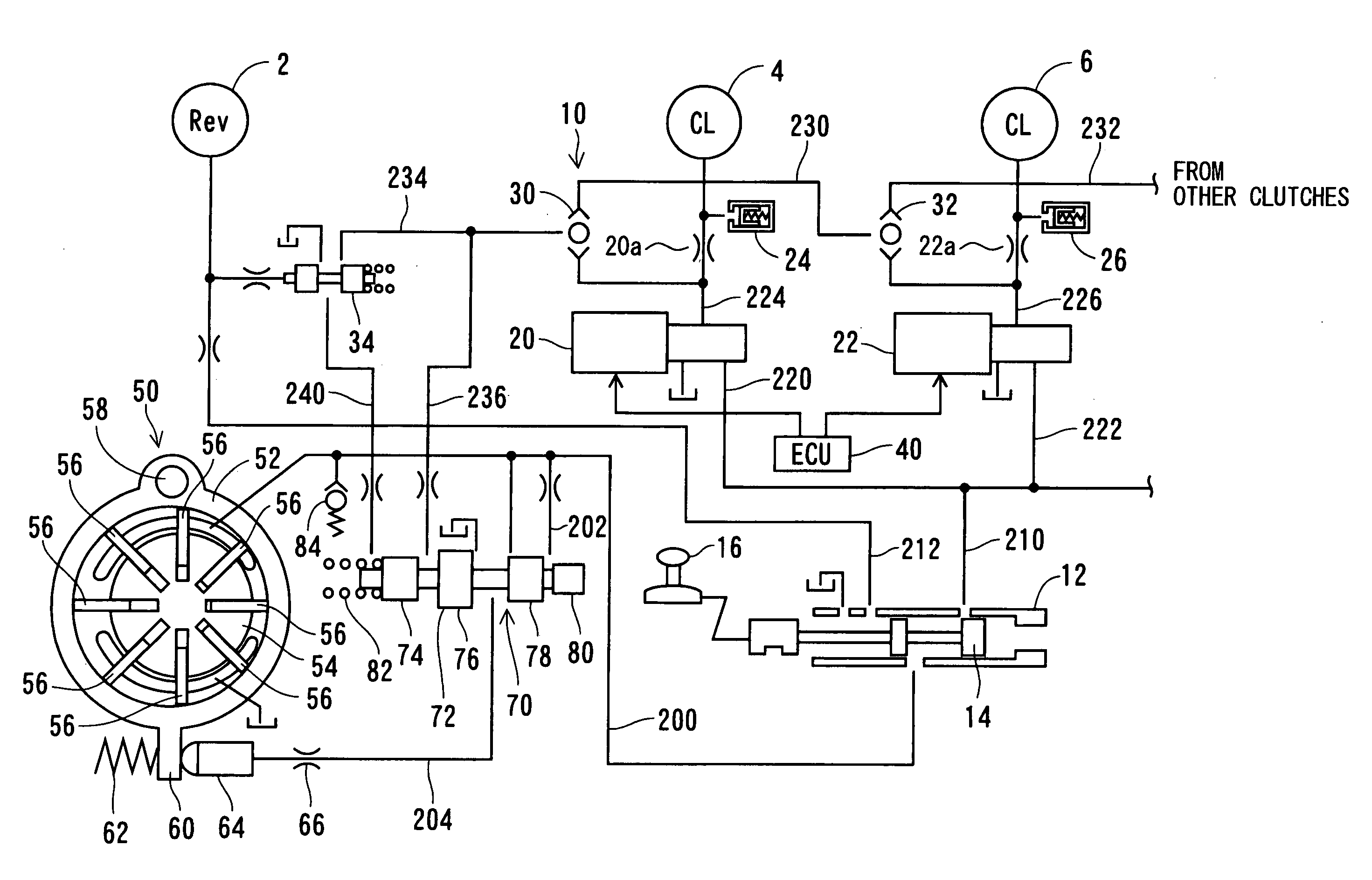
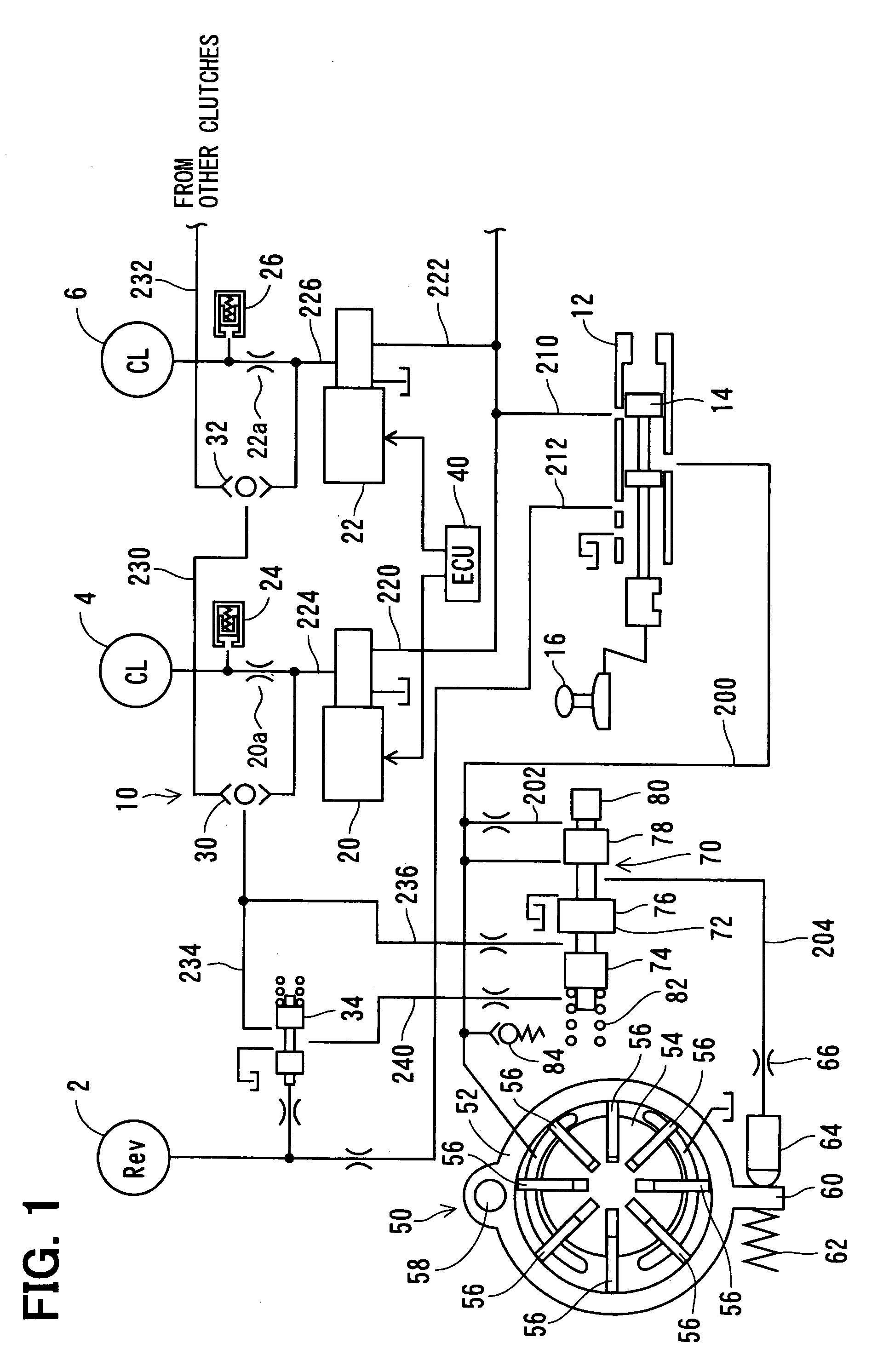
[0030]An automatic transmission control device according to a first embodiment of the present invention will be explained with reference to FIG. 1.

[0031]In FIG. 1, a reverse clutch 2, a clutch 4, another clutch 6 and other clutches not shown in the drawing as well as brakes also not shown in the drawing are friction elements, each of which is engaged or released (disengaged) by hydraulic pressure to change a transmission gear.

[0032]A spool 14 of a manual valve 12 is moved back and forth when a shift range is changed by a driver via a shift lever 16, so that a communication between a hydraulic pressure line 200 and a pressure line 210 for a forward movement is changed to a communication between the hydraulic pressure line 200 and a pressure line 212 for a backward movement, or vice versa. A pressurized working fluid (working oil) is discharged from a pump 50 into the hydraulic pressure line 200. A discharge fluid pressure of the pump 50 is applied to a line pressure control valve 70 ...


PUM


Abstract

In an automatic transmission control device, multiple electromagnetic valves control fluid pressure of working fluid to be applied to multiple friction elements of an automatic transmission device, so that a transmission gear is changed by engaging some of the friction gears and/or disengaging the other of the friction elements. The electromagnetic valve controls its output pressure in such a manner that the output pressure is temporally increased when starting the transmission gear change. A maximum fluid pressure is selected from the output pressures of the multiple electromagnetic valves and is applied to a pressure control valve, which controls a fluid control pressure applied to a capacity varying device for changing a discharge amount of a pump. As a result, the fluid pressure applied to the friction elements can be rapidly increased at proper timings.

Description

CROSS REFERENCE TO RELATED APPLICATION[0001]This application is based on Japanese Patent Application No. 2007-38836, which is filed on Feb. 20, 2007, the disclosure of which is incorporated herein by reference.FIELD OF THE INVENTION[0002]The present invention relates to an automatic transmission control device for hydraulically controlling a transmission mechanism of an automatic transmission device for a vehicle.BACKGROUND OF THE INVENTION[0003]An automatic transmission control device is known in the art, for example, as disclosed in the following Japanese Patent Publications:[0004]JP 2003-254420[0005]JP 2005-127435[0006]JP H5-312250[0007]In the above automatic transmission control device, oil pressure to be applied to friction elements, such as clutches and brakes, which form a transmission mechanism of an automatic transmission device, is controlled so that a transmission gear is changed by bringing the friction elements into engagement while bringing other friction elements out ...

Claims


Application Information

Patent Timeline
Patent Type & Authority Applications(United States)
IPC IPC(8): B60W10/10G06F19/00F16H59/42F16H59/72F16H61/00
CPCY10T477/688F16H61/0021
Inventor TAKAGI, AKIRA
Owner DENSO CORP
Why Eureka
Try Eureka