Discharge tray apparatus

a technology of discharging tray and apparatus, which is applied in the direction of instruments, visual presentation using printers, electrographic processes, etc., can solve the problems of short time of tray shift operation in which the above tray shift operation is performed, and the recording paper will not be properly placed at a different position, so as to reduce the rotational speed of eccentric cam, simple configuration, and the effect of speed

Active Publication Date: 2008-08-07
SHARP KK
View PDF9 Cites 8 Cited by
  • Summary
  • Abstract
  • Description
  • Claims
  • Application Information

AI Technical Summary

Benefits of technology

[0017]The present invention was made in view of the circumstances described above, and it is an object thereof to provide a discharge tray apparatus in which, when performing a tray shift operation of a discharge tray at high speed, it is possible to prevent a recording paper bundle that has been placed on the discharge tray from becoming disorganized.

Problems solved by technology

If this is not done, the recorded recording paper will not be properly placed at a different position on the discharge tray of the discharge tray apparatus for each copy unit.
Therefore, due to increased processing speed as described above in copiers and the like, the tray shift operation time in which the above tray shift operation is performed becomes very short.

Method used


Image

  • Discharge tray apparatus
  • Discharge tray apparatus
  • Discharge tray apparatus

Examples


Embodiment Construction

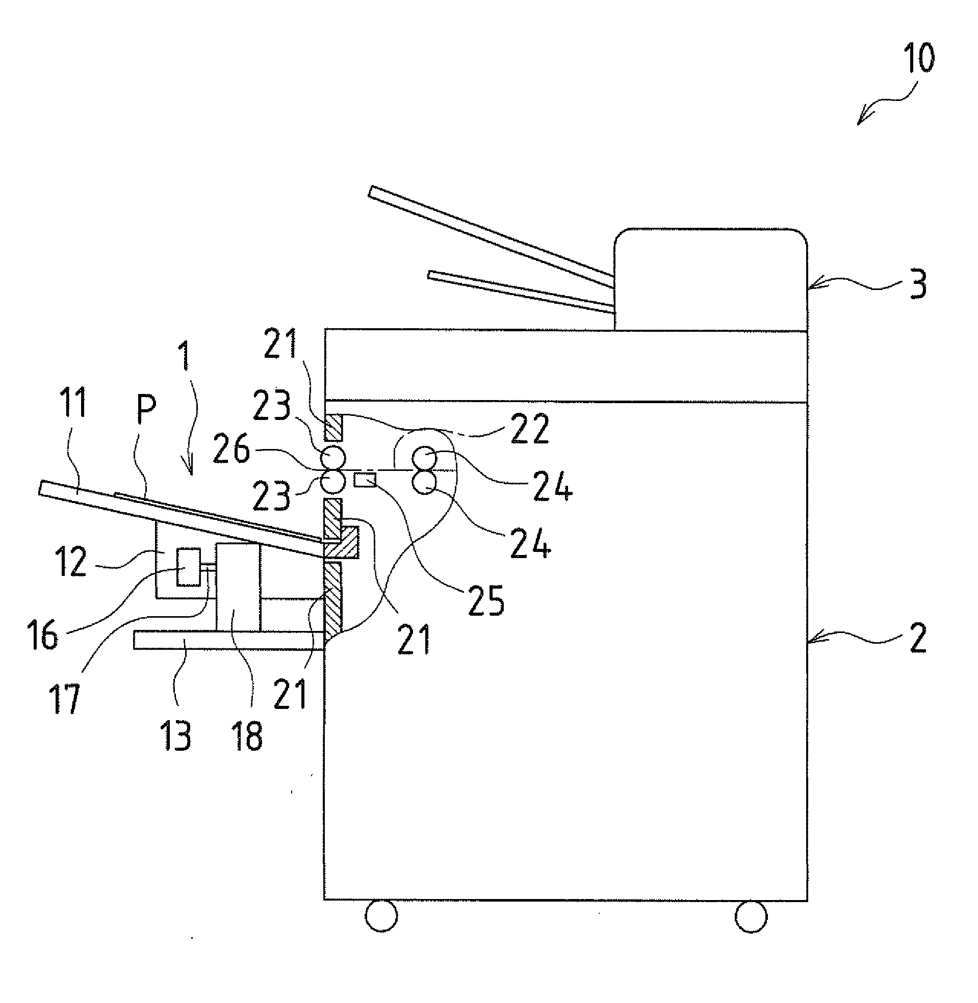
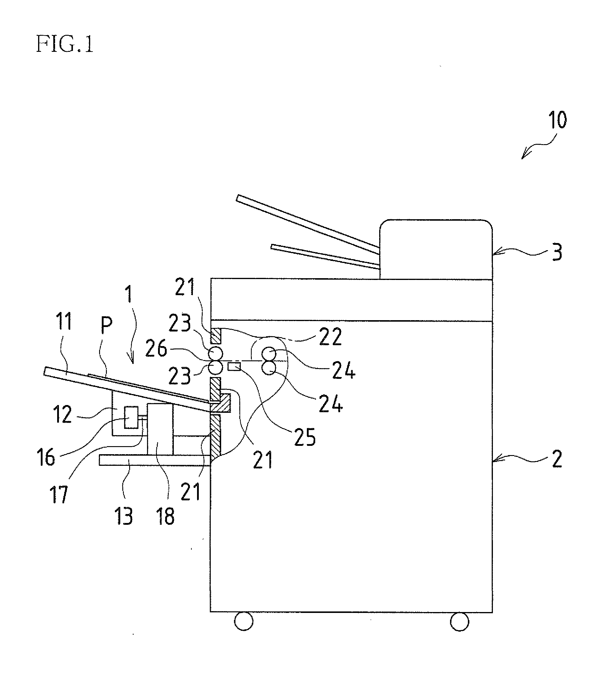
[0054]Hereinafter, a discharge tray apparatus of an embodiment of the present invention will be described with reference to the drawings, using as an example a copier provided with the discharge tray apparatus of the present embodiment. FIG. 1 is right side view of a copier 10. This copier 10 is configured with an image recording apparatus 2, an original reading apparatus 3 provided above the image recording apparatus 2, and a discharge tray apparatus 1 of an embodiment of the present invention provided in a front portion case 21 of the image recording apparatus 2.

[0055]In the copier 10, from an original in the form of a piece of paper that has been placed in the original reading apparatus 3, image information is read with the original reading apparatus 3, which is provided with an optical scanner, and based on this image information, a recording image is formed on a recording paper P by the image recording apparatus 2. More specifically, in the image recording apparatus 2, a photos...


PUM

PropertyMeasurementUnit
speedaaaaaaaaaa
movement speedaaaaaaaaaa
distanceaaaaaaaaaa

Abstract

A discharge tray apparatus according to one embodiment of the present invention is a discharge tray apparatus wherein a plurality of sheets of recording paper that have been successively transported at a fixed speed and a fixed interval, discharged from a discharge opening, and have landed on a discharge tray, are received and placed onto the discharge tray, the discharge tray apparatus being provided with a discharge tray moving means that performs a tray shift operation that moves the discharge tray in a horizontal direction approximately perpendicular to the discharge direction, such that after a preceding paper successively transported earlier has been placed on the discharge tray, a succeeding paper succeedingly transported after the preceding paper is placed at a position different from the placement position of the preceding paper on the discharge tray. This discharge tray moving means performs the tray shift operation with a decelerating movement that reduces the movement speed of the discharge tray just before movement of the discharge tray stops.

Description

CROSS-REFERENCE TO RELATED APPLICATION[0001]This application claims priority under 35 U.S.C. § 119(a) on Japanese Patent Application No. 2007-027184 filed in Japan on Feb. 6, 2007, the entire contents of which are herein incorporated by reference.BACKGROUND OF THE INVENTION[0002]1. Field of the Invention[0003]The present invention relates to a discharge tray apparatus that is provided in a copier or the like configured based on an image recording apparatus, the discharge tray apparatus housing recorded recording paper that has been recorded with the image recording apparatus.[0004]2. Description of the Related Art[0005]Presently, copiers, facsimile machines, printing apparatuses, and the like are absolutely necessary for paperwork in offices. These copiers, facsimile machines, printing apparatuses, and the like are configured based on an image recording apparatus, and recorded paper that has been recorded with this image recording apparatus is released, discharged, and placed on a d...

Claims


Application Information

Patent Timeline
Patent Type & Authority Applications(United States)
IPC IPC(8): G06K15/16
CPCB65H31/02B65H33/08B65H2301/4219B65H2403/512G03G2215/0089B65H2405/351B65H2801/06G03G15/6547G03G2215/00421B65H2405/11151
Inventor TSUJI, MASARU
Owner SHARP KK
Why Eureka
Try Eureka