
Linear vibration motor

Inactive Publication Date: 2012-07-05
MPLUS
View PDF4 Cites 12 Cited by
  • Summary
  • Abstract
  • Description
  • Claims
  • Application Information

AI Technical Summary

Benefits of technology

[0023]The vibrator part may further include a damper coupled with the contact part of the printed circuit board to be opposite to the fixing part in order to prevent noise and impact when contacting with the fixing part.

Problems solved by technology

However, the linear vibration motor designed to be vibrated in a vertical direction has a limitation in thickness in that it is not linearly vibrated until a space of about 4 mm in thickness in which the weight body installed in the vibrator may move up and down in order to generate vibrations.

Method used


Image

  • Linear vibration motor
  • Linear vibration motor
  • Linear vibration motor

Examples


Embodiment Construction

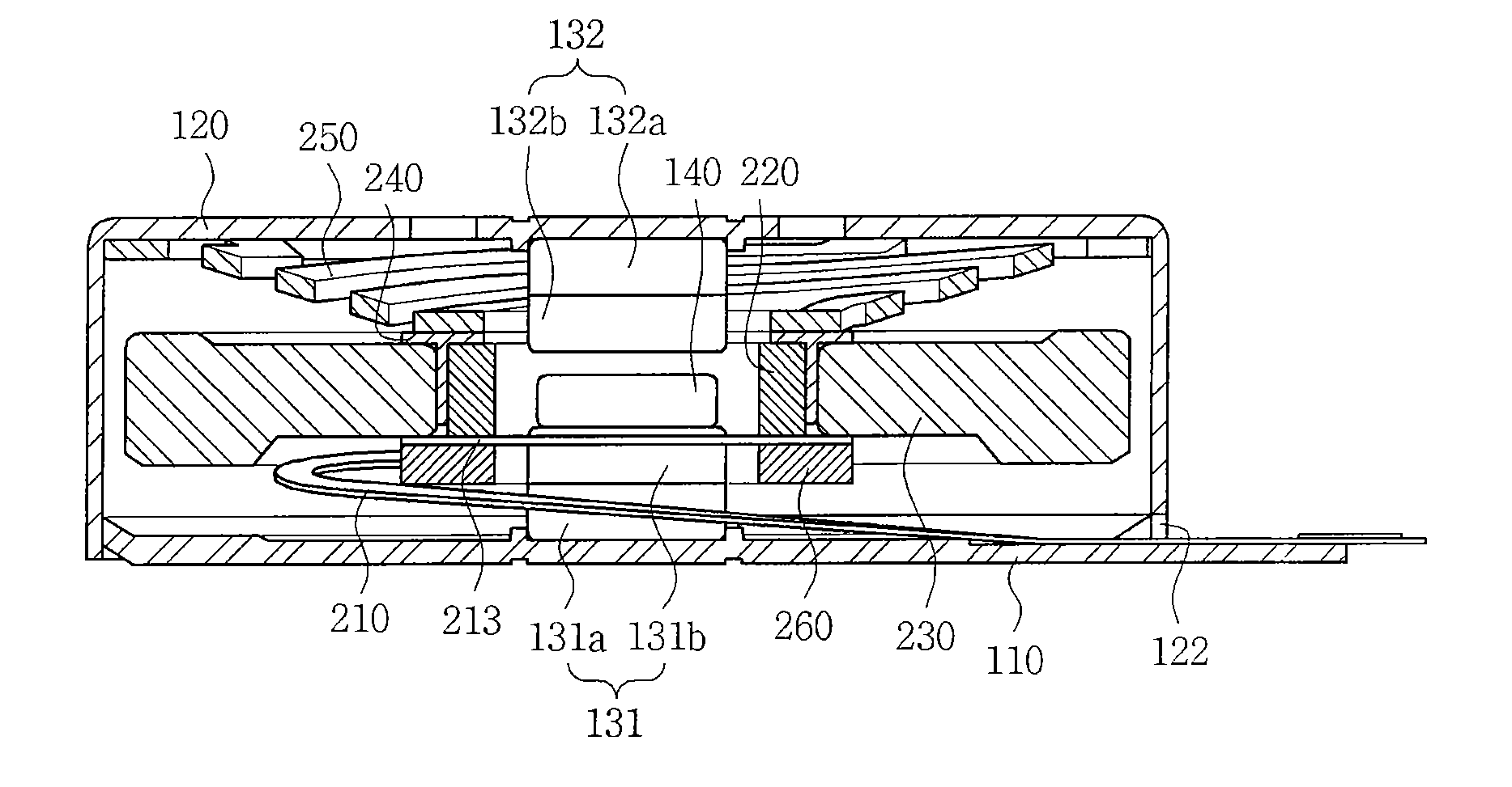
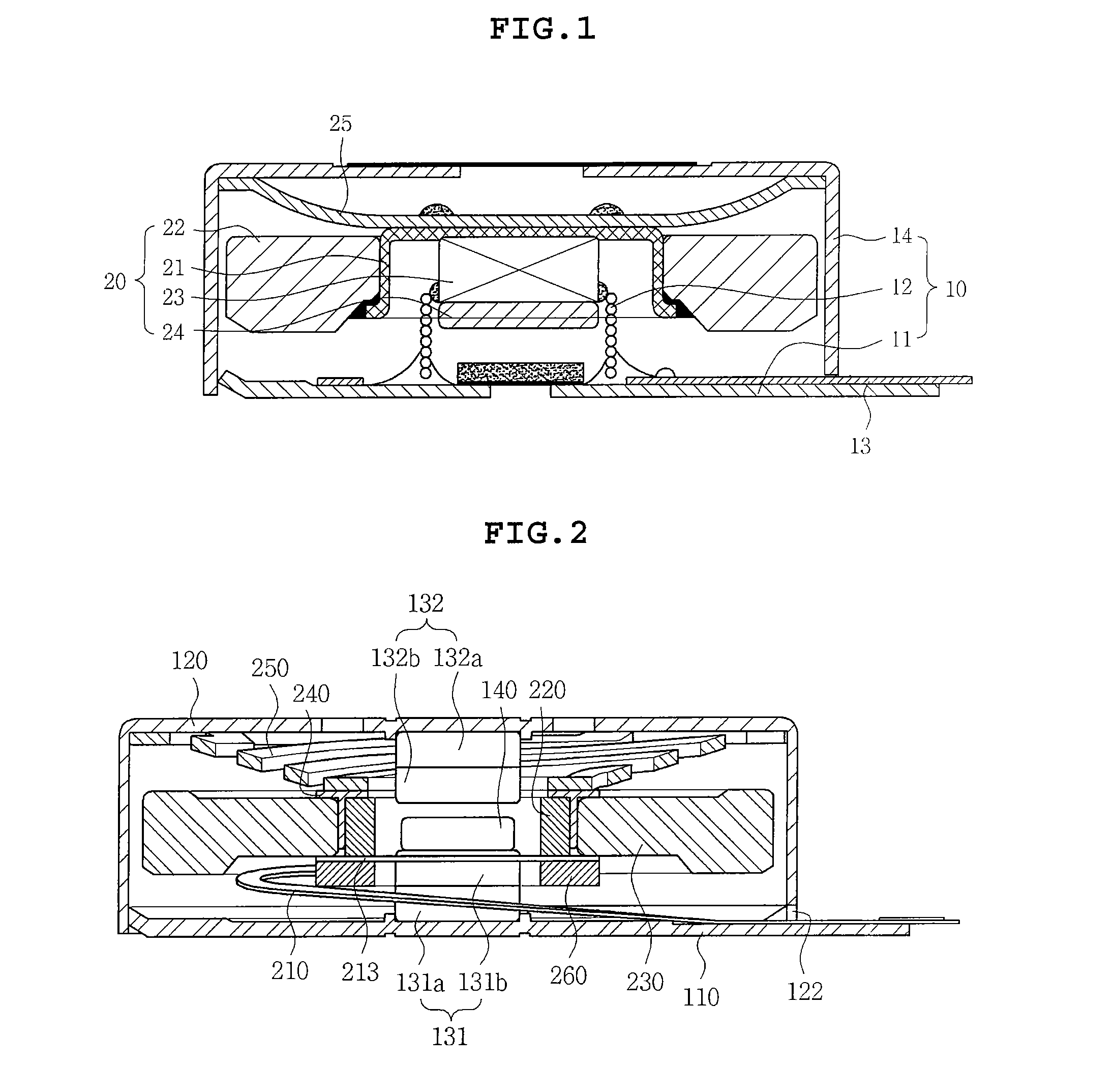
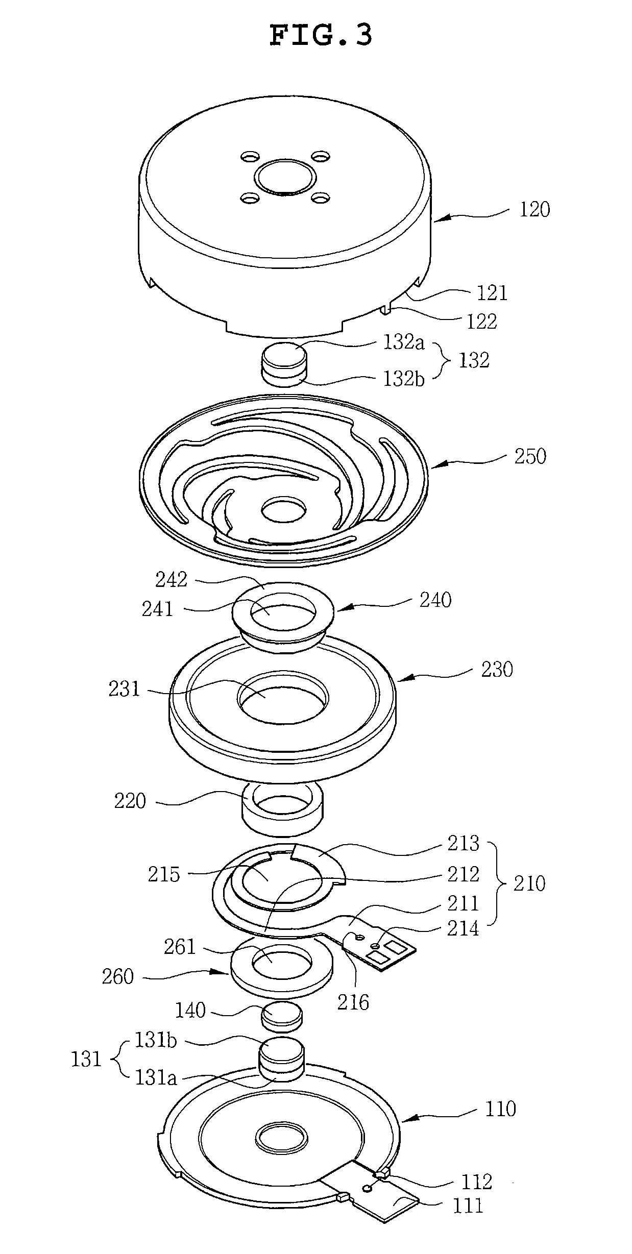
[0030]The above and other objects, features and advantages of the present invention will be more clearly understood from the following detailed description taken in conjunction with the accompanying drawings. In the specification, in adding reference numerals to components throughout the drawings, it is to be noted that like reference numerals designate like components even though components are shown in different drawings. Terms used in the specification, ‘first’, ‘second’, etc. can be used to describe various components, but the components are not to be construed as being limited to the terms. The terms are only used to differentiate one component from other components. Further, in describing the present invention, a detailed description of related known functions or configurations will be omitted so as not to obscure the subject of the present invention. Further, when it is determined that the detailed description of the known art related to the present invention may obscure the ...


PUM


Abstract

Disclosed herein is a linear vibration motor including: a fixing part including a magnet; and a vibrator part including a coil corresponding to the magnet and a printed circuit board coupled with the coil, wherein one end of the printed circuit board is coupled with the fixing part and the other end thereof is coupled with the coil.

Description

CROSS REFERENCE TO RELATED APPLICATION[0001]This application claims the benefit of Korean Patent Application No. 10-2010-0139975, filed on Dec. 31, 2010, entitled “Linear Vibration Motor” which is hereby incorporated by reference in its entirety into this application.BACKGROUND OF THE INVENTION[0002]1. Technical Field[0003]The present invention relates to a linear vibration motor.[0004]2. Description of the Related Art[0005]A general vibration motor, which is a component that uses a principle of generating electromagnetic force and converts electrical energy into mechanical vibrations, is mounted in mobile communication terminals, portable terminals, or the like, to silently notify a call to a user.[0006]Recently, a linear vibration motor has been generally used as a vibration motor. The linear vibration motor is generally disposed at a corner portion of a device to generate vibrations in a direction vertical to an object receiving vibrations.[0007]As shown in FIG. 1, the linear vib...

Claims


Application Information

Patent Timeline
IPC IPC(8): H02K33/00
CPCH02K33/18B06B1/045
Inventor LEE, KWANG HYUNGYOON, AN SOOOH, HWA YOUNG
Owner MPLUS
Features
  • Generate Ideas
  • Intellectual Property
  • Life Sciences
  • Materials
  • Tech Scout
  • Unparalleled Data Quality
  • Higher Quality Content
  • 60% Fewer Hallucinations
Learn More