
Simplified jaw assembly for a clamp meter

a clamp meter and jaw assembly technology, applied in the field of electrical test tools, can solve the problems of raising reliability problems, difficult to individually disconnect the wire of interest, and inconvenient wire connection to connect the current meter

Active Publication Date: 2012-07-05
JOHN FLUKE MFG CO INC
View PDF13 Cites 14 Cited by
  • Summary
  • Abstract
  • Description
  • Claims
  • Application Information

AI Technical Summary

Problems solved by technology

In many cases, however, disconnecting the wire to connect the current meter can be inconvenient.
For example, the wire can be tightly grouped in a bundle with several other wires making it difficult to individually disconnect the wire of interest.
Another example of the inconvenience is where a terminal to which the wire is connected is not conveniently located or is inaccessible, requiring the wire to be cut for the current meter to be connected in series.
It is time consuming to reconnect the two ends of the cut wire after a measurement is taken, and can be dangerous in situations where relatively high current is carried by the wire.
Additionally, the integrity of the wire is compromised by cutting and reconnecting, thus, potentially raising reliability problems.
However, problems with reading the measurement can arise where the wire is difficult to reach or cannot be readily singled-out from amongst adjacent wires.
It is therefore more difficult to use the known jaw assembly to select an individual wire from a group of wires because the cross-section of the known jaw assembly is enlarged due to the location of the joints between the housing pieces and the separate end caps.

Method used


Image

  • Simplified jaw assembly for a clamp meter
  • Simplified jaw assembly for a clamp meter
  • Simplified jaw assembly for a clamp meter

Examples


Embodiment Construction

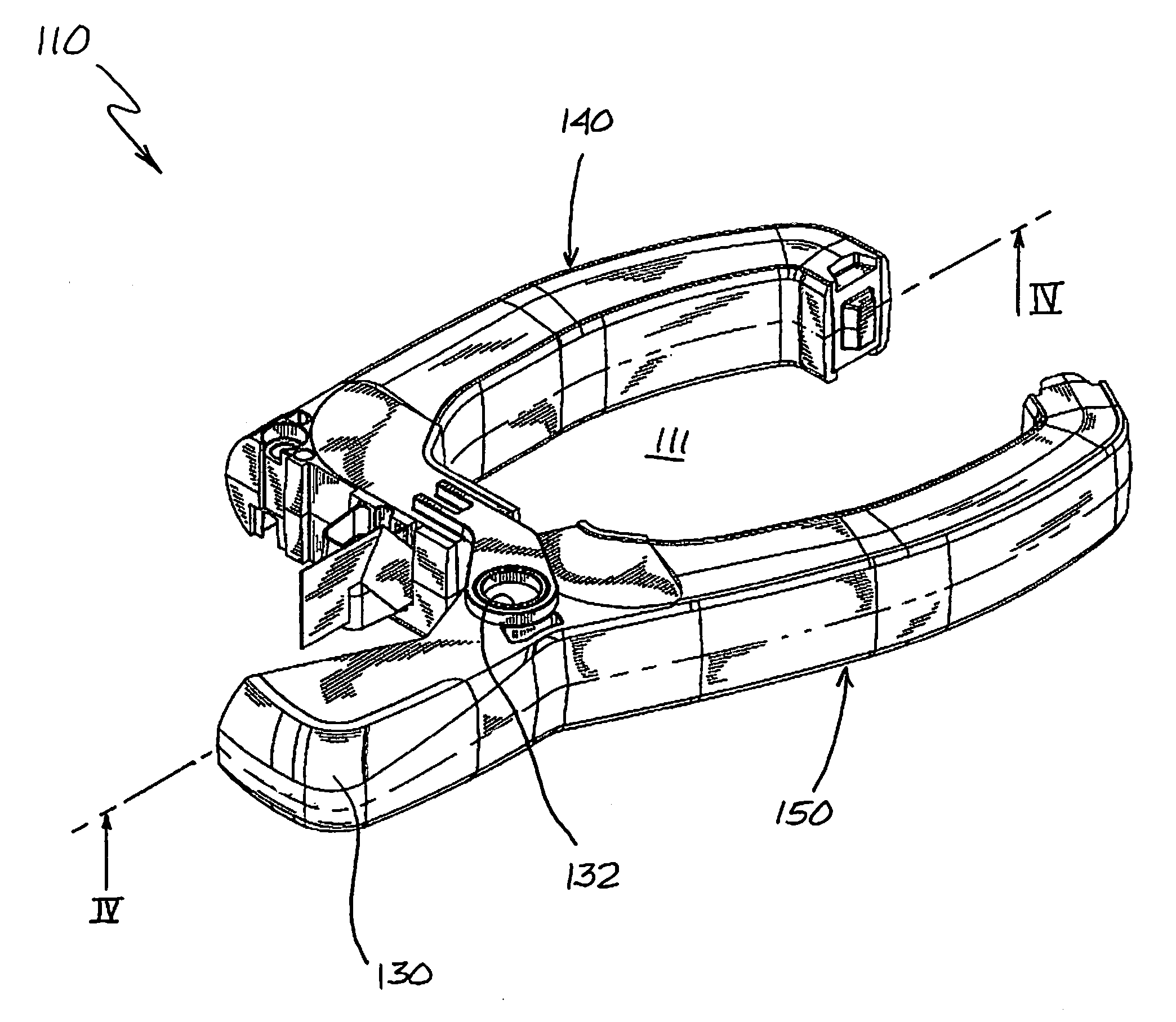
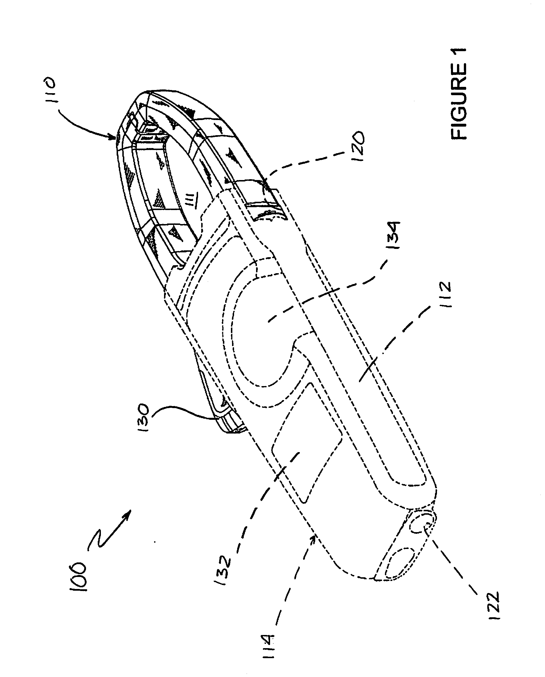
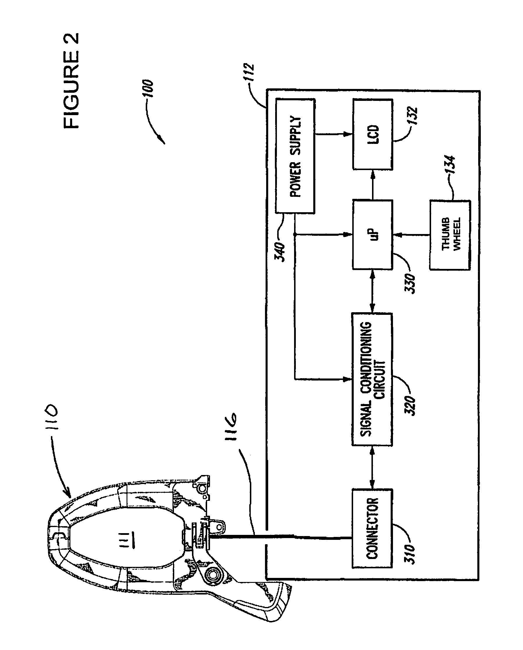
[0015]The following description and drawings are illustrative and are not to be construed as limiting. Numerous specific details are described to provide a thorough understanding of the disclosure. However, in certain instances, well-known or conventional details are not described in order to avoid obscuring the description.

[0016]Without intent to further limit the scope of the disclosure, examples of instruments, apparatus, methods and their related results according to the embodiments of the present disclosure are given below. Reference in this specification to “one embodiment” or “an embodiment” means that a particular feature, structure, or characteristic described in connection with the embodiment is included in at least one embodiment of the disclosure. The appearances of the phrase “in one embodiment” in various places in the specification are not necessarily all referring to the same embodiment, nor are separate or alternative embodiments mutually exclusive of other embodime...


PUM


Abstract

A current clamp meter includes a current meter body and a jaw assembly. The jaw assembly is configured so that the current clamp meter may be used to reach and readily single-out a desired wire from amongst adjacent wires.

Description

CROSS-REFERENCE TO RELATED APPLICATION(S)[0001]This patent application is a continuation-in-part of U.S. patent application Ser. No. 29 / 382,283, filed on 30 Dec. 2010, entitled “Clamp Meter Jaws;” and claims the benefit under 35 U.S.C. §119 of U.S. Provisional Patent Application No. 61 / 429,384, filed on 3 Jan. 2011, entitled “Simplified Jaw Assembly for a Clamp Meter.” Both of these applications are incorporated herein in their entirety by reference.TECHNICAL FIELD[0002]This invention generally relates to electronic test tools, and more specifically, to a current clamp meter including a jaw assembly that has a reduced cross-section to aid a user in selecting a wire for measuring current through the wire.BACKGROUND OF THE INVENTION[0003]Electrical current can be measured by connecting a current meter in series with the wire. In many cases, however, disconnecting the wire to connect the current meter can be inconvenient. For example, the wire can be tightly grouped in a bundle with se...

Claims


Application Information

Patent Timeline
Patent Type & Authority Applications(United States)
IPC IPC(8): G01R1/20
CPCG01R1/22
Inventor WORONES, JEFF
Owner JOHN FLUKE MFG CO INC
Learn More