Inkjet recording apparatus and recording method

a recording apparatus and inkjet technology, applied in the direction of printing, other printing apparatus, etc., can solve the problems of product cost and maintenance cost increase, image formation requires a long time,

Active Publication Date: 2012-07-05
TOSHIBA TEC KK
View PDF8 Cites 12 Cited by
  • Summary
  • Abstract
  • Description
  • Claims
  • Application Information

AI Technical Summary

Problems solved by technology

However, if the number of times for which scanning is performed to print the white ink is increased to be greater than

Method used


Image

  • Inkjet recording apparatus and recording method
  • Inkjet recording apparatus and recording method
  • Inkjet recording apparatus and recording method

Examples


first embodiment

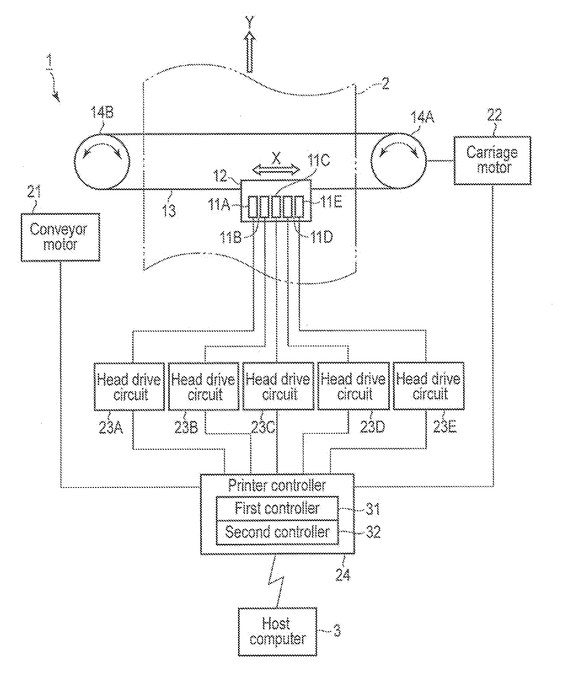
[0023]FIG. 1 is a block diagram showing a configuration of a main part of the inkjet recording apparatus 1. In FIG. 1, an arrow X denotes a main scanning direction, and an arrow Y denotes a sub-scanning direction. Along the main scanning direction X, printing proceeds when a recording medium 2 and inkjet heads 11A to 11E move relatively to each other. The sub-scanning direction Y is perpendicular to the main scanning direction X.

[0024]The inkjet recording apparatus 1 conveys a recording medium 2 in the sub-scanning direction Y by a conveyor mechanism (not shown) which is driven by a conveyor motor 21 as a drive source. The recording medium 2 is not limited to any particular material, thickness, or size insofar as image formation is available by the inkjet recording apparatus 1.

[0025]The inkjet recording apparatus 1 comprises a head carriage 12 on which five inkjet heads 11A, 11B, 11C, 11D, and 11E are mounted. The head carriage 12 is attached to a carriage belt 13. The carriage bel...

second embodiment

[0089]According to the second embodiment, an image is formed by ejecting, at most, two ink drops 81 for from each of inkjet heads 11A, 11B, 11C, and 11D which respectively eject color inks (K, C, M, and Y). Hardware part of an inkjet recording apparatus 1 is the same as that in the first embodiment. Therefore, FIGS. 1 to 10 and Table 1 are also referred to in the second embodiment, and detailed descriptions thereof will be omitted.

[0090]In the second embodiment, as shown in FIG. 13, the inkjet heads 11A, 11B, 11C, and 11D which respectively eject the color inks (K, C, M, and Y) form an image of print data by ejecting two ink drops (12 pL) or one ink drop (6 pL) at high resolution of 1,200 dpi in the main scanning direction X at a speed of 167,000 dots per second. In brief, images are expressed in two gradations. Such ejection control is performed by a first controller 31.

[0091]In contrast, an inkjet head 11E which ejects a white ink (W) forms an image as a ground by sequentially emi...


PUM


Abstract

According to one embodiment, an inkjet recording apparatus includes a plurality of inkjet heads of a multi-drop method, a first controller, and a second controller. The first controller controls ejection of ink drops from a first inkjet head for ejecting a first ink for which print resolution is required, in a manner that a number of ink dots formed in a main scanning direction is great, and that the number of ink drops ejected for each one of the ink dots is small. The second controller controls ejection of the ink drops from a second inkjet head for ejecting a second ink for which coverage over a recording surface of the recording medium is required, in a manner that a number of ink dots formed in the main scanning direction is small, and that the number of ink drops ejected for each of the ink dots is great.

Description

CROSS-REFERENCE TO RELATED APPLICATIONS[0001]This application is based upon and claims the benefit of priority from Japanese Patent Application No. 2011-000121, filed on Jan. 4, 2011, the entire contents of which are incorporated herein by reference.FIELD[0002]Embodiments described herein relate generally to an inkjet recording apparatus comprising a multi-drop-type inkjet head, and a recording method thereof.BACKGROUND[0003]An ink jet recording apparatus which forms a color image on a white ground uses color inks, such as a black ink (K), a cyan ink (C), a magenta ink (M), and an yellow ink (Y), and a white ink. A white ground is formed on a print surface of a recording medium with the white ink, and thereafter, a color image is formed.[0004]The color image formed by the ink jet recording apparatus improves more in quality as coverage of the print surface with the white ink increases. Therefore, the ink jet recording apparatus is devised to raise the coverage. For example, a number...

Claims


Application Information

Patent Timeline
IPC IPC(8): B41J29/38
CPCB41J29/38B41J2/2117
Inventor TAKAMURA, JUN
Owner TOSHIBA TEC KK
Why Eureka
Try Eureka