
LED Lighting Assembly With Detachable Power Module and Lighting Fixtures with Same

a technology of led lighting and power modules, which is applied in the field of led lighting assemblies, can solve the problems of significant loss of electrical energy necessary for incandescent lamps and insufficient fluorescent lighting

Inactive Publication Date: 2012-07-05
CHINA LIGHTING ENG
View PDF0 Cites 8 Cited by
  • Summary
  • Abstract
  • Description
  • Claims
  • Application Information

AI Technical Summary

Benefits of technology

[0003]Accordingly, there is a need in the art for a readily-changed lighting assembly for lighting fixtures, which provides economical operating features. It is to such that the present invention is directed.

Problems solved by technology

A significant amount of the electrical energy necessary to operate incandescent lamps is lost as waste heat.
Often, however, fluorescent lighting is not as satisfactory due to the color of the light that is produced.

Method used


Image

  • LED Lighting Assembly With Detachable Power Module and Lighting Fixtures with Same
  • LED Lighting Assembly With Detachable Power Module and Lighting Fixtures with Same
  • LED Lighting Assembly With Detachable Power Module and Lighting Fixtures with Same

Examples


Embodiment Construction

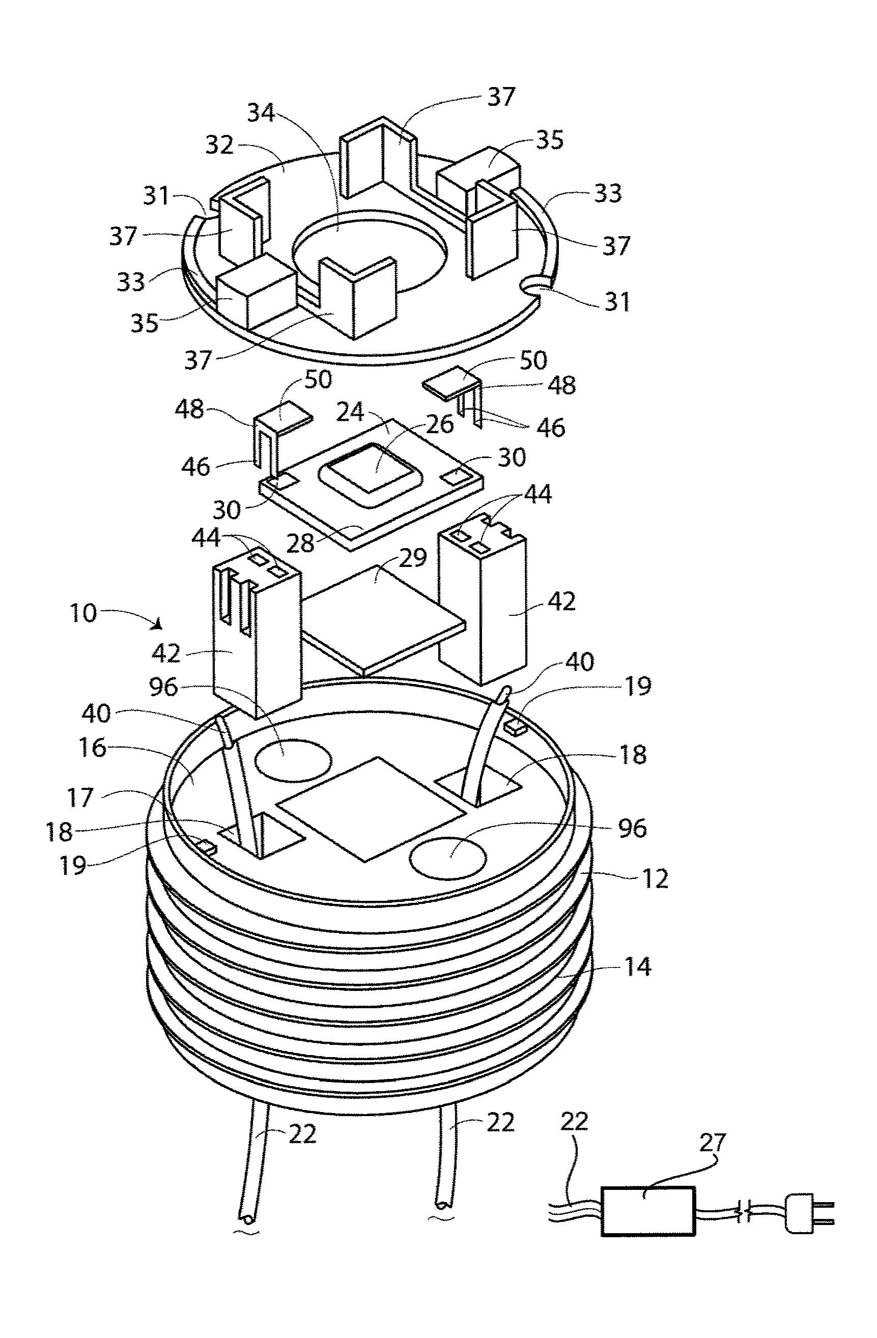
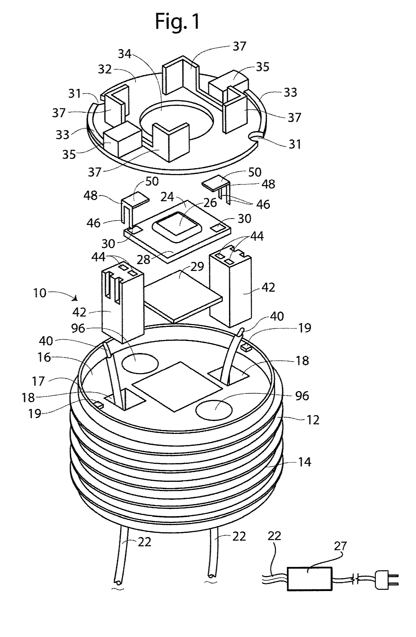
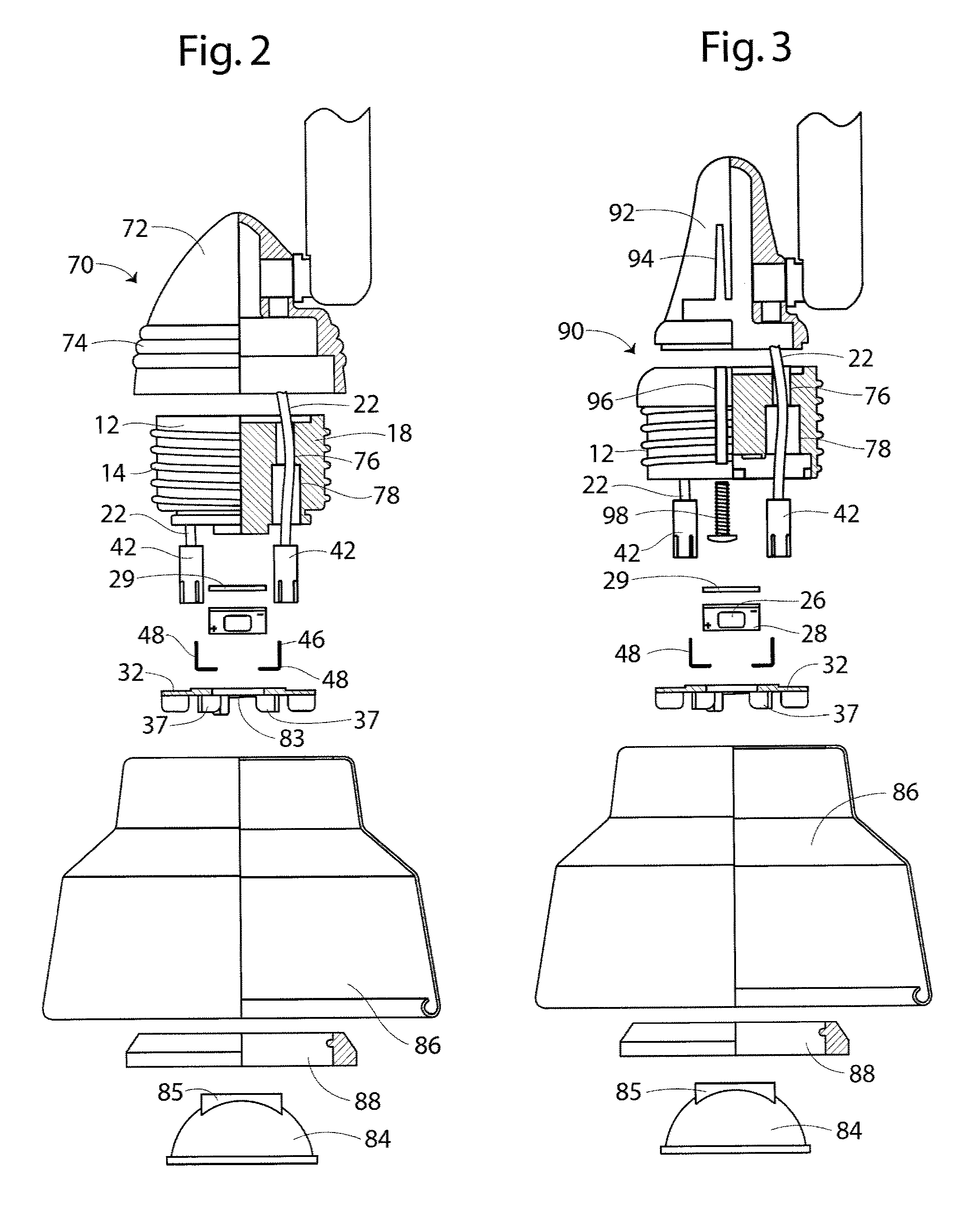
[0013]With reference to the drawings in which like reference numerals indicate like parts, FIG. 1 illustrates in exploded perspective view an illustrative embodiment of an LED lighting assembly 10 in accordance with the present invention for installation in a lighting fixture. The LED light assembly 10 includes a heat sink 12 having a threaded exterior 14 and a receiving side 16. In the illustrated embodiment, the receiving side 16 is recessed and a perimeter wall 17 extends axially. A lug 19 projects from an inner surface of the wall 17. A pair of first passageways 18 extend through the heat sink 12. An alternate embodiment provides a single first passageway 18. A pair of electrical conductors 22 extend through the first passageways 18 for electrical communication with a supply of electrical current (not illustrated).

[0014]A ceramic base 24 and an attached LED chip 26 define an LED power package 28. The LED chip 26 includes a conventional LED device that illuminates upon supply of ...


PUM


Abstract

An LED light assembly has a heat sink and electrical conductors for electrical communication with a supply of electricity. A ceramic base with an LED chip attaches to the heat sink. Electricity communicating pads in the ceramic base each operatively connect with the LED chip and with the electrical connectors. A plate defines an aperture and overlies the ceramic base for passage of light from the LED chip. The LED light assembly attaches to a housing of a lighting fixture that may include a light shade.

Description

TECHNICAL FIELD[0001]The present invention relates to luminaries for lighting applications. More particularly, the present invention relates to lighting fixtures with LED lamp assemblies having readily replaced LED lamps and drivers.BACKGROUND[0002]While incandescent and fluorescent lighting provide illumination for buildings, signage, and the like, environmental and operational factors are leading to development of alternative illumination devices. A significant amount of the electrical energy necessary to operate incandescent lamps is lost as waste heat. Fluorescent lamps have operation temperatures that are cooler and thus have less heat loss arising from converting electrical energy to light. Often, however, fluorescent lighting is not as satisfactory due to the color of the light that is produced. Incandescent lamps generally have a shorter life than that of wattage-equivalent fluorescent lamps.[0003]Accordingly, there is a need in the art for a readily-changed lighting assembl...

Claims


Application Information

Patent Timeline
Patent Type & Authority Applications(United States)
IPC IPC(8): F21V29/00
CPCF21K9/30F21V1/00F21V5/04F21V7/00F21V17/06F21V17/14F21V29/89F21V19/045F21V23/002F21V29/004F21Y2101/02H01R13/6658F21V29/85F21V17/164F21V19/04F21K9/20F21Y2115/10F21V29/70
Inventor HING CHUEN, ALLAN KWONGZHANG, ZHU JUN
Owner CHINA LIGHTING ENG
Learn More