
Vehicular lighting assembly

a technology for lighting assemblies and vehicles, applied in vehicle headlamps, vehicle sub-unit features, optical signalling, etc., can solve problems such as wiring requirements of vehicles

Active Publication Date: 2018-12-20
JOHNSON ELECTRIC SA
View PDF6 Cites 1 Cited by
  • Summary
  • Abstract
  • Description
  • Claims
  • Application Information

AI Technical Summary

Benefits of technology

The present invention aims to provide a better vehicle lighting assembly that can adjust for the angle at which the lights are mounted on a vehicle. This will improve the overall quality of the vehicle's lighting.

Problems solved by technology

In doing so, this can substantially reduce the wiring requirements of the vehicular lighting assembly, which can be the most common cause of failure in such a system.

Method used


Image

  • Vehicular lighting assembly
  • Vehicular lighting assembly
  • Vehicular lighting assembly

Examples


Embodiment Construction

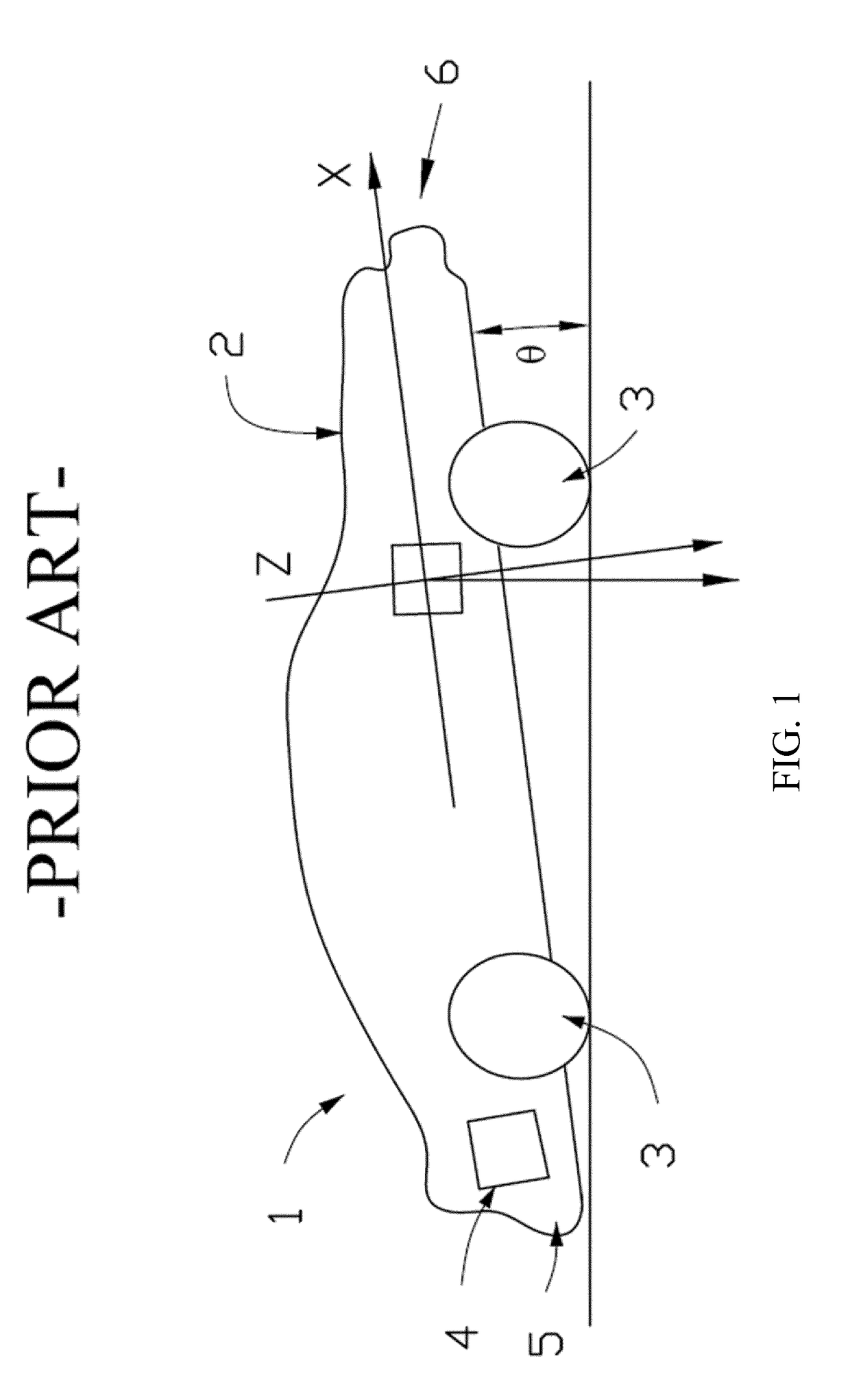
[0047]Referring firstly to FIG. 1, there is illustrated a motor vehicle as known in the art, indicated globally at 1. Such a motor vehicle 1 has a chassis 2 having a plurality of wheels 3 attached for rotation thereto.

[0048]Under normal load conditions, it is assumed that a horizontal axis of the wheeled chassis 2, indicated as X in FIG. 1, will remain horizontal to the ground, with a vertical, normal axis Z being parallel to the direction of gravitational force on the vehicle.

[0049]However, as illustrated in FIG. 1, under conditions of asymmetric load on the chassis 2, for instance, where a significant mass 4 is placed in the boot or trunk 5 of the motor vehicle 1, the pitch of the motor vehicle 1 may be significantly affected. As can be seen, the front end 6 of the motor vehicle 1 pitches significantly upwards, such that the axis X of the chassis 2 is inclined at an angle θ to the horizontal.

[0050]As the front end 6 of the motor vehicle 1 is pitched upwards, so too is the directio...


PUM


Abstract

A vehicular lighting assembly for compensating for the change in light emission angle due to load on a vehicle. The assembly included at least one lighting element, an actuator associated with the or each lighting element for adjusting a light emission angle of light emitted therefrom relative to the vehicle with which the vehicular lighting assembly is associated, and an actuator housing in which the actuator is housed. A vehicular-pitch-determining sensor is then arranged to indirectly determine a pitch of the vehicle, and associated with a controller for controlling an actuation of the actuator in response to a vehicular pitch as determined by the vehicular-pitch-determining sensor. A vehicular lighting system, pitch-compensation actuation unit, motor vehicle and method of altering the angle of light emission from the headlamps of a motor vehicle are also provided.

Description

CROSS-REFERENCE TO RELATED APPLICATIONS[0001]This application is a national stage entry of International application PCT / EP2016 / 078915 filed Nov. 25, 2016, which claimed priority to GB application 1520877.0 filed Nov. 26, 2015.FIELD OF THE INVENTION[0002]The present invention relates to a vehicular lighting assembly, in particular but not necessarily exclusively for use as part of the headlights of a motor vehicle. The invention further relates to a vehicular lighting system, to a pitch-compensation actuation unit, to a motor vehicle having such a vehicle lighting assembly, and to a method of altering the angle of light emission from the headlamps of a motor vehicle.BACKGROUND OF THE INVENTION[0003]If a motor vehicle has an asymmetric load on its chassis, for instance, if the boot or trunk of the vehicle is heavily laden, then the vehicle will pitch out of the horizontal plane. Since vehicular headlights are calibrated to a given load which is deemed horizontal, any pitch of the veh...

Claims


Application Information

Patent Timeline
Patent Type & Authority Applications(United States)
IPC IPC(8): B60Q1/115B60Q1/076B60Q1/00
CPCB60Q1/115B60Q1/076B60Q1/0023B60Q2300/132B60Q2300/112B60Q2300/114B60Y2400/303
Inventor WEBER, DANIEL
Owner JOHNSON ELECTRIC SA
Learn More