Double pivot vehicle mirror assembly

a mirror and double-pitch technology, applied in the field of mirror assemblies, can solve the problems of high cost of simultaneous attaining a fixed position, and achieve the effect of small support force, enhanced support arm and/or mirror head, and high resistance torqu

Inactive Publication Date: 2006-12-07
LANG MEKRA NORTH AMERICA LLC
View PDF5 Cites 6 Cited by
  • Summary
  • Abstract
  • Description
  • Claims
  • Application Information

AI Technical Summary

Benefits of technology

[0009] The above objective is accomplished in accordance with the present invention by providing a mirror assembly having a support arm, a mirror head, and two hinges connecting the support arm and the mirror head. The first hinge allows a pivoting of the mirror head about its axle of rotation only in one direction, and the second hinge permits a pivoting of the mirror head about its axle of rotation only in a second direction of rotation, which is opposite to the first. Preferably, each hinge pivots only in one direction. In this way, the construction of both hinges is less complex. The first and / or second hinge may incorporate a detent which limits rotation in either the first or the second direction. Such a detent can, for example, be made mechanically or be provided with a friction fit. Thus, a desired second detent can also be the detent inherent in the other hinge arrangement. The large lever arms, which result therefrom, assure, with relatively small support forces, sufficiently high resistance torques. In this way, completion of a pivoting opposite to the allowable direction of turning is provided. By means of limiting the turning motion to only one direction, it is advantageously possible to fix the mirror head satisfactorily in its operational position, since in these two hinges, in the respective direction, high forces are accepted.
[0010] The first and / or second hinge can include a torsion spring. The springs, in a constructive, simple, and economical manner provide a pivoting in the allowable direction and otherwise affix the mirror head securely in its operational position. Further, the springs allow the mirror head to return accurately to its operational position following a safety displacement.
[0011] In a particularly advantageous embodiment, upon a pivoting of the mirror head about the axis of one hinge, the hinge connection between the mirror head and the carrier arm is released. In this way, for example, the axis of the first hinge prevents a further pivoting about the axis of the second hinge counter to the second rotational direction beyond the limited operational positioning. In the case of a pivoting in the second rotational direction, to the contrary, the connection of the first hinge releases itself.
[0012] In a preferable manner, the support arm and / or the head of the mirror can be enhanced with a bearing structure, preferably of metal construction. If this is coated, for example, with a material, such as plastic, and the coating can be applied by spraying, the result is a light, aerodynamically favorable, and uniformly stable assembly of the mirror, and vibration of the mirror is reduced. Particularly preferable, the first and / or the second hinge can be hingedly and reliably attached to this structure.
[0013] In another advantageous embodiment, the support arm comprises a first and a second part. Between the said first and second support arm part, a third hinge is present, the axis of rotation of which extends itself vertically during the mounting of the mirror. This allows an additional pivot direction of the mirror assembly to the side or to the front of the vehicle. The overall dimensioning allows an advantageous reduction of length for, as an example, loading on a ship, parking, or the like. This extra pivoting can be effected by a motor, or may be manual.

Problems solved by technology

Hinges which permit swinging in both directions, and enable a simultaneous attainment of a fixed position are expensive.

Method used


Image

  • Double pivot vehicle mirror assembly
  • Double pivot vehicle mirror assembly
  • Double pivot vehicle mirror assembly

Examples


Embodiment Construction

[0020] Referring now in more detail to the drawings, the invention will now be described in more detail.

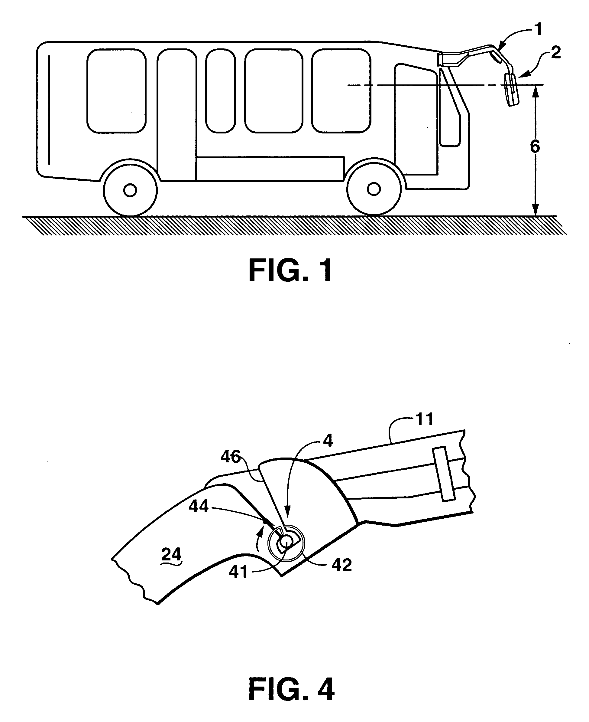
[0021] As is shown in FIG. 1, a mirror assembly, designated generally as A, in accord with the present invention is illustrated installed on a vehicle. The mirror assembly includes a support arm 1 and a mirror head 2. Mirror head 2 of the assembly, is illustrated in a position which has not been pivoted, and at least partially extends into safety zone 6 above the ground. Since mirror head 2, in accordance with the invention, is pivotal in alternate positions above the safety zone, damage is avoided even in the case of an impact against an obstruction within the safety zone. Especially traumatic damage to persons, who are within the said safety zone, such as, bus passengers, can be avoided.

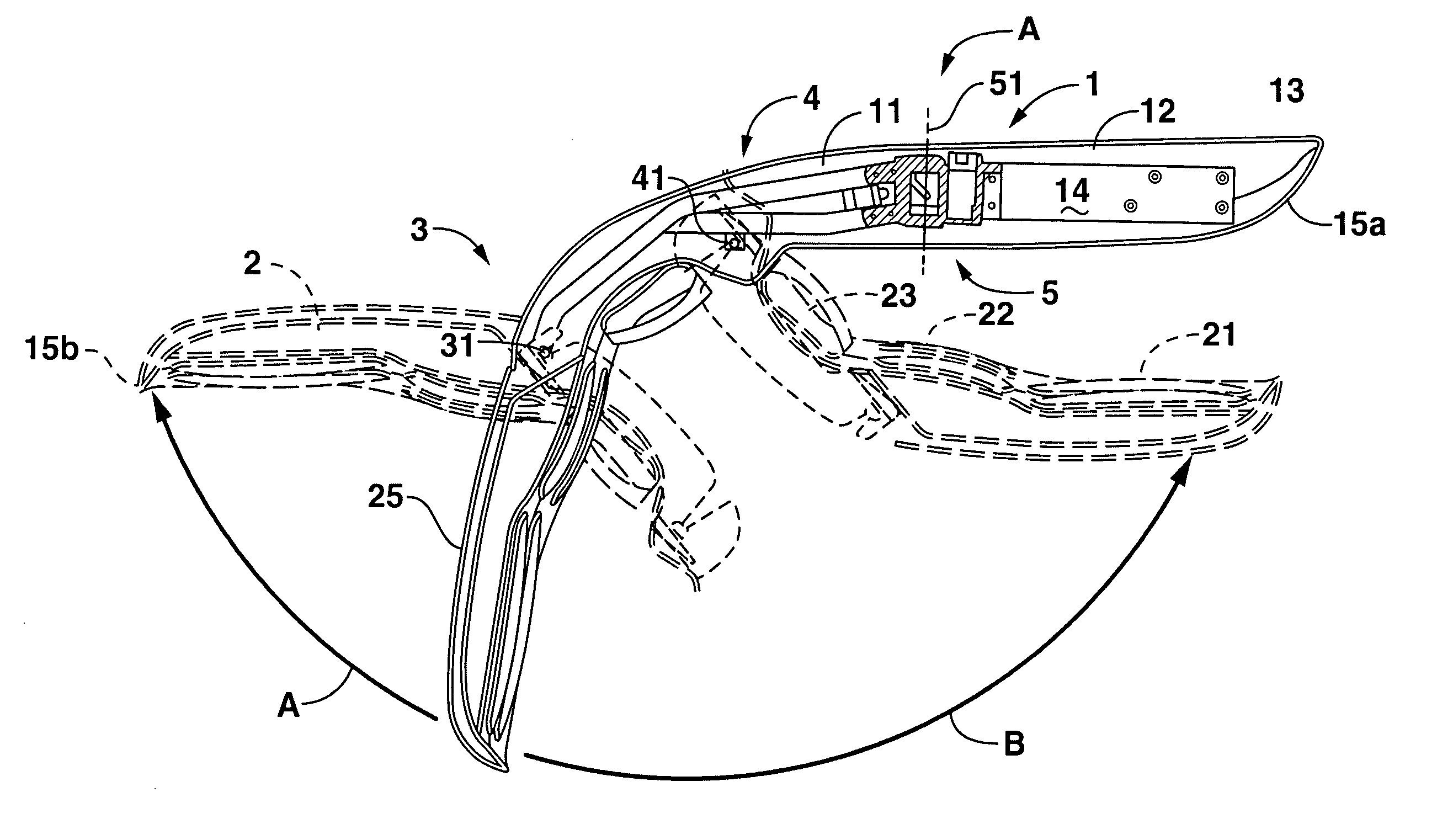
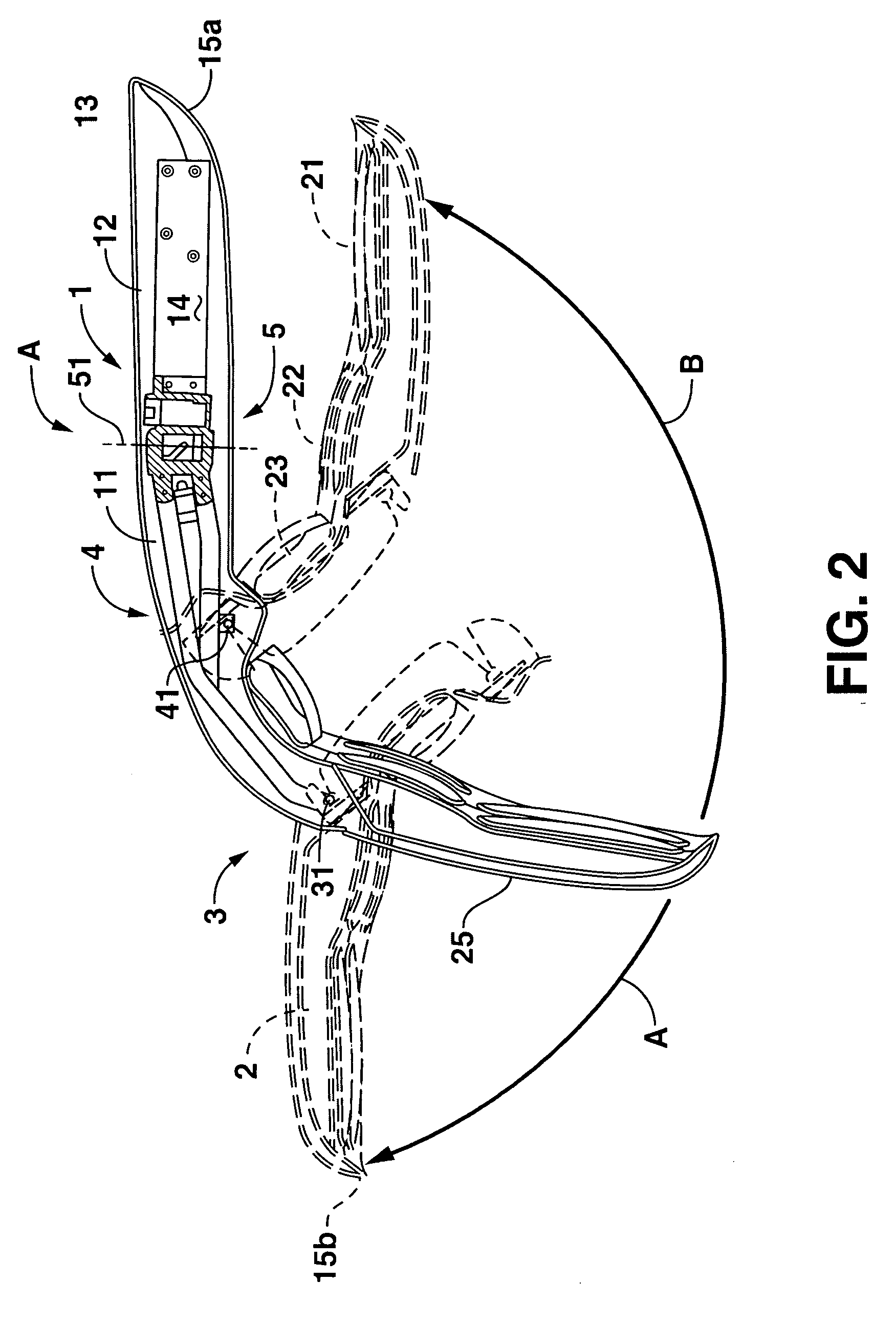
[0022]FIG. 2 illustrates, in a side profile view, a mirror assembly in accordance with an embodiment of the present invention in an operating condition (solid lines) and two alternate positions...


PUM


Abstract

A mirror assembly especially designed for commercial vehicles including a support arm, a mirror head pivotally affixed to the support arm by first and second hinges having a pivot axis. The axes extend horizontally and transverse to the direction of vehicle travel. The first hinge allows a pivoting of the mirror head about its pivot axis only in a first direction A and the second hinge permits a pivoting of the mirror head only in a second direction B which is opposite to the direction A. By this means, it is possible that the two hinges can be simple and rugged in construction.

Description

[0001] The present invention concerns a mirror assembly for a vehicle, in particular for a commercial vehicle. [0002] The support arm of rearview mirrors in commercial vehicles, like a city bus, is commonly extended forward from the chassis at an essentially horizontal level when the mirror head hangs downward from the forward end of a support arm, they are known as “horn-mirrors,” especially when applied to buses. Horn-mirrors provide better aerodynamics and simple fabrication as well as an advantageous field of view which encompasses a wide arc. [0003] If, as in the case of “low-floor” buses, a part of the support arm and / or the mirror extend into a safety zone, this zone normally covers a span from the ground level to about 2 meters above, the mirror must be adjusted as to height for the protection of both mirror and persons as may be waiting within a said safety zone. [0004] EP 0 895 897 B1 proposes a single hinge attachment so that the mirror can be swiveled about a single hori...

Claims


Application Information

Patent Timeline
Patent Type & Authority Applications(United States)
IPC IPC(8): A47G1/24B60R1/06
CPCB60R1/0617B60R1/06B60J5/0404B60R1/081B60R2011/004
Inventor LANG, WERNERPOPP, ALBRECHTREIMCHEN, RICHARD
Owner LANG MEKRA NORTH AMERICA LLC
Why Eureka
Try Eureka