Transmission with Resistance Torque Control

Inactive Publication Date: 2008-06-26
TORVEC INC
View PDF24 Cites 0 Cited by
  • Summary
  • Abstract
  • Description
  • Claims
  • Application Information

AI Technical Summary

Benefits of technology

[0022]When vehicle acceleration is desired, the minimal fluid passage that connects the input and output ports of the hydraulic machine is closed off by the pressure valve so that piston movement is limited by the just-mentioned minimal flow of blow-by as pressure is built up by the small angular adjustment of the swash plate that is rapidly rotating at the speed of the control gear. The minimal blow-by, which is less than 5% of the volume of fluid blocked within the machine by the closed valve, permits the angle of the rotating swash plate to be increased, increasing the resistance torque that slows the rotation of the control gear. The minimal blow-by at 1700 rpm is preferably less than 1 gal/min and is conventionally replenished to the low pressure side of the hydraulic machine by a small charge pump.
[0023]A transmission of the present invention provides a significant gain in engine efficiency by using the just-described s

Problems solved by technology

The preference for this design of hydraulic machine cannot be over emphasized, since presently available commercial hydraulic pumps and motors are considered unacceptable for use with the subject invention because: (1) they are much larger and much heavier than the Torvec long-piston machines; (2) they are incapable of providing the high speeds needed for automotive use; (3) they do not have the start-up torque capabilities of the Torvec long-piston machines; (4) their “break-away” torque makes them inappropriate for

Method used


Image

  • Transmission with Resistance Torque Control
  • Transmission with Resistance Torque Control
  • Transmission with Resistance Torque Control

Examples


Embodiment Construction

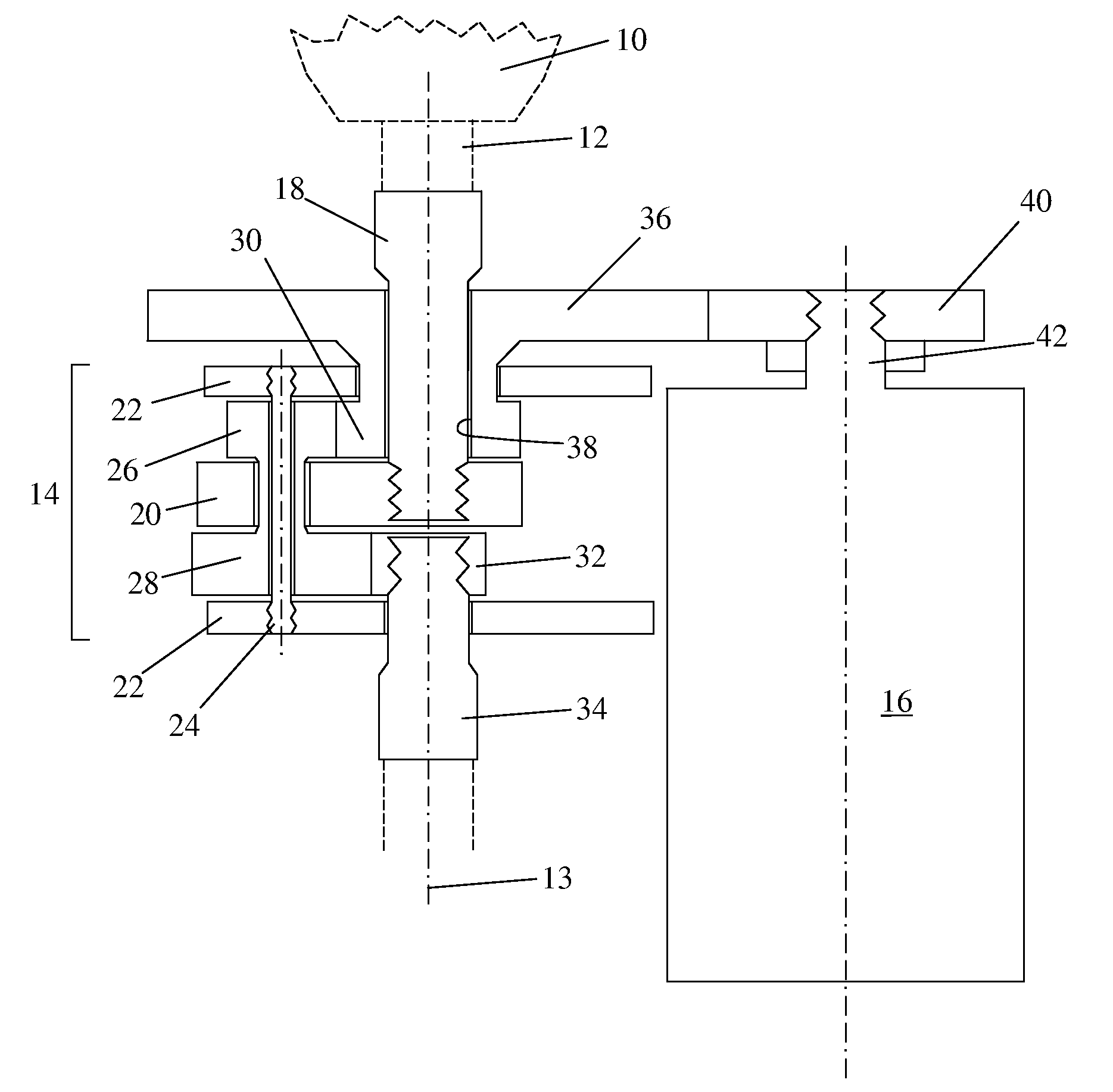
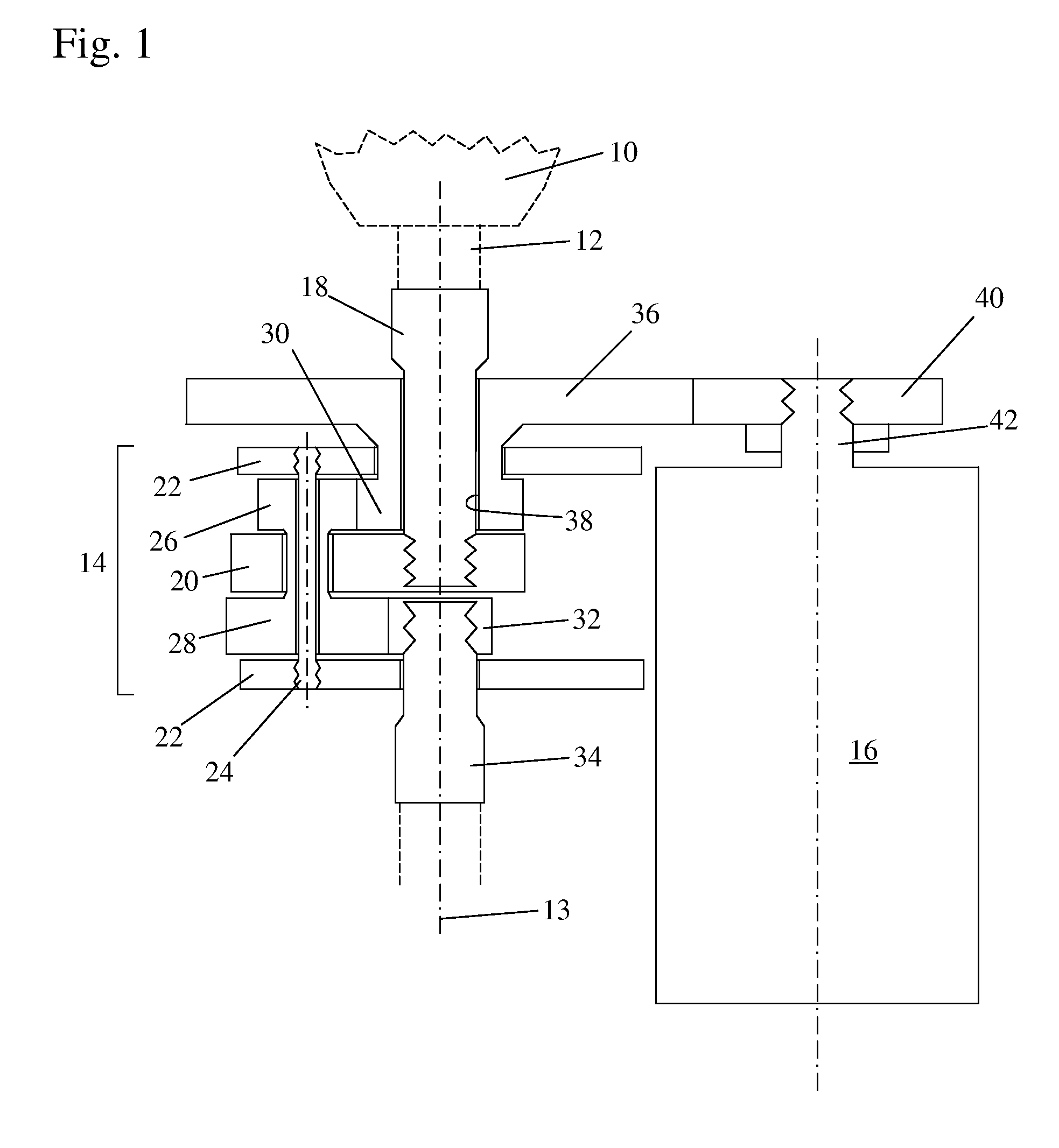
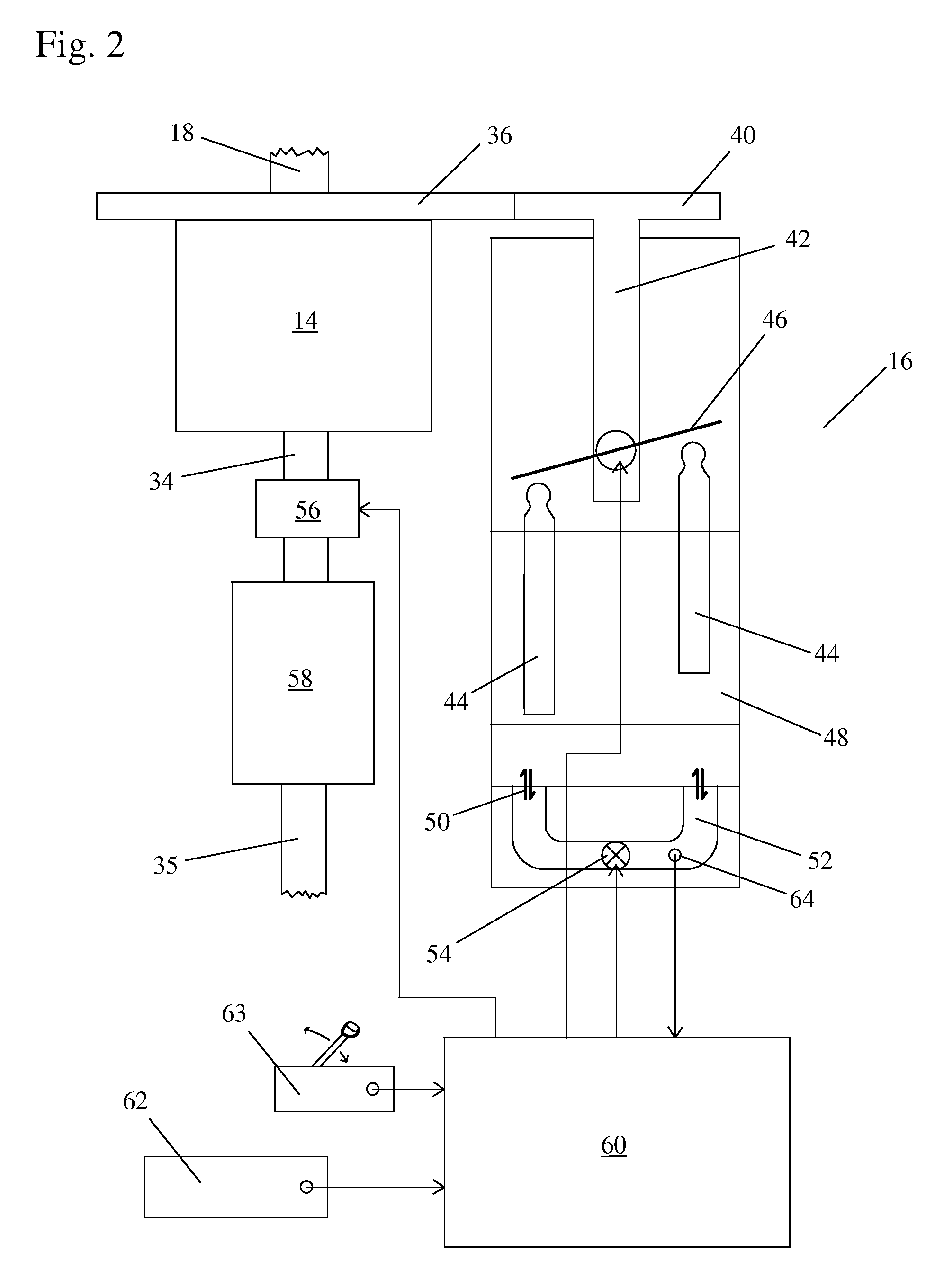
[0032]FIG. 1 and FIG. 2 are schematic diagrams of a remarkably small and compact transmission in embodiments of the present invention attached to the crankshaft 12 of a primary engine 10 that provides an input for an orbital gear complex 14 which is in combination with a rotary control device that is disclosed in this preferred embodiment as a hydraulic jack machine 16. An input shaft 18 is splined to engine crankshaft 12, both of which are aligned along a first axis 13. A central drive plate 20 is positioned between the two end plates 22, and these just-named three elements together form the orbital web of the transmission that also rotates about first axis 13. Input shaft 18 is also splined to central drive plate 20. End plates 22 support the respective ends of orbit shaft 24 that carries a cluster gear that includes cluster gear 26 and cluster gear 28. While a preferred orbital gear complex comprises at least two or three sets of orbit shafts 24 and cluster gears 26 / 28, only one ...


PUM


Abstract

The transmission includes a minimal-orbiter gear complex and a single infinitely-variable rotary control device. The minimal orbiter includes only a control gear and an output gear interconnected by the different gearing portions of at least one cluster gear supported by an orbiting web responsive to an input drive provided by a primary engine. The rotary control device may be any kind of apparatus that is capable of providing resistance torque that can match the torque of the primary engine to slow and stop the control gear of the orbital complex. In a preferred embodiment disclosed, the rotary control device is a hydraulic jack machine having a drive shaft connected to an adjustable swash plate that provides primary control of the flow of fluid through the machine.

Description

REFERENCE TO RELATED APPLICATIONS[0001]The subject matter in this application is related to the subject matter in co-pending U.S. patent application Ser. No. 11 / 153,112, filed Jun. 15, 2005, entitled “ORBITAL TRANSMISSION WITH GEARED OVERDRIVE”. The aforementioned application is hereby incorporated herein by reference.BACKGROUND OF THE INVENTION[0002]1. Field of the Invention[0003]The invention pertains to the field of automotive transmissions. More particularly, the invention pertains to an automotive transmission with orbital gearing and a variable sun gear control.[0004]2. Description of Related Art[0005]Known conventional transmissions use the vehicle's engine as the primary control for making changes in vehicle speed.[0006]The manual transmission uses a clutch to change the gear ratio, with the engine being completely disconnected from the transmission momentarily during each level of gear change, and also with the engine being quickly revved up to fairly high rpm during each l...

Claims


Application Information

Patent Timeline
IPC IPC(8): B60W10/10
CPCF16H3/72Y10T477/619Y10T477/675
Inventor GLEASMAN, JAMES Y.GLEASMAN, KEITH E.GABEL, DONALD
Owner TORVEC INC
Why Eureka
Try Eureka