Hydraulic system of a clutch of a motor vehicle transmission

a technology of hydraulic system and transmission, which is applied in the direction of belt/chain/gearing, mechanical equipment, and gear control, etc., can solve the problems of hydraulic fluid foaming and torque, and achieve the effects of increasing the drag moment, reducing the power effective, and increasing the consumption

Inactive Publication Date: 2009-07-30
DR ING H C F PORSCHE AG
View PDF1 Cites 1 Cited by
  • Summary
  • Abstract
  • Description
  • Claims
  • Application Information

AI Technical Summary

Benefits of technology

[0014]Moreover, a permanent throughflow would increase drag moments. This applies particularly to double clutch transmissions, since these even make it possible to engage a gear in a second part transmission while torque transfer between the engine and transmission output is still taking place via the first part transmission. The gear preselected and engaged in this situation in the second part transmission is also designated as a shadow gear. The clutch of the second part transmission is in this case driven by the common transmission output and, due to the throughflow, experiences a drag moment which reduces the power effective on the wheels of the vehicle (a power loss of 0.3 to 0.5 kW was observed at 1500 rev / min in a specific engine) and increases the consumption.

Problems solved by technology

At the same time, due to the on-demand opening of the hydraulic valve, undesirable secondary effects, which may occur in the event of a permanent flow through the double clutch, are restricted to an extent which has to be taken into account for cooling purposes.
These undesirable secondary effects include a foaming of the hydraulic fluid and an occurrence of drag moments (torques).

Method used


Image

  • Hydraulic system of a clutch of a motor vehicle transmission
  • Hydraulic system of a clutch of a motor vehicle transmission
  • Hydraulic system of a clutch of a motor vehicle transmission

Examples


Embodiment Construction

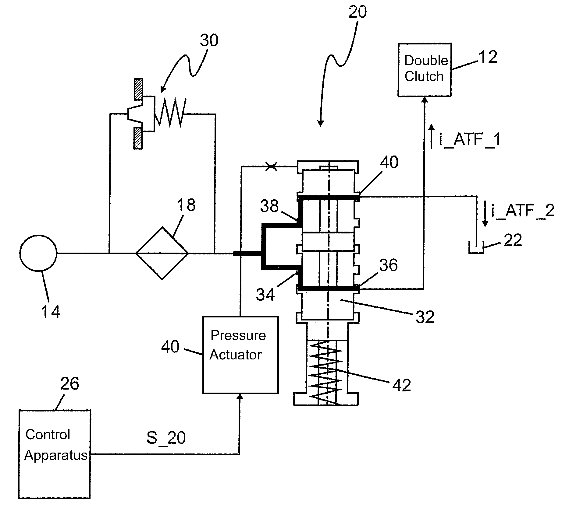
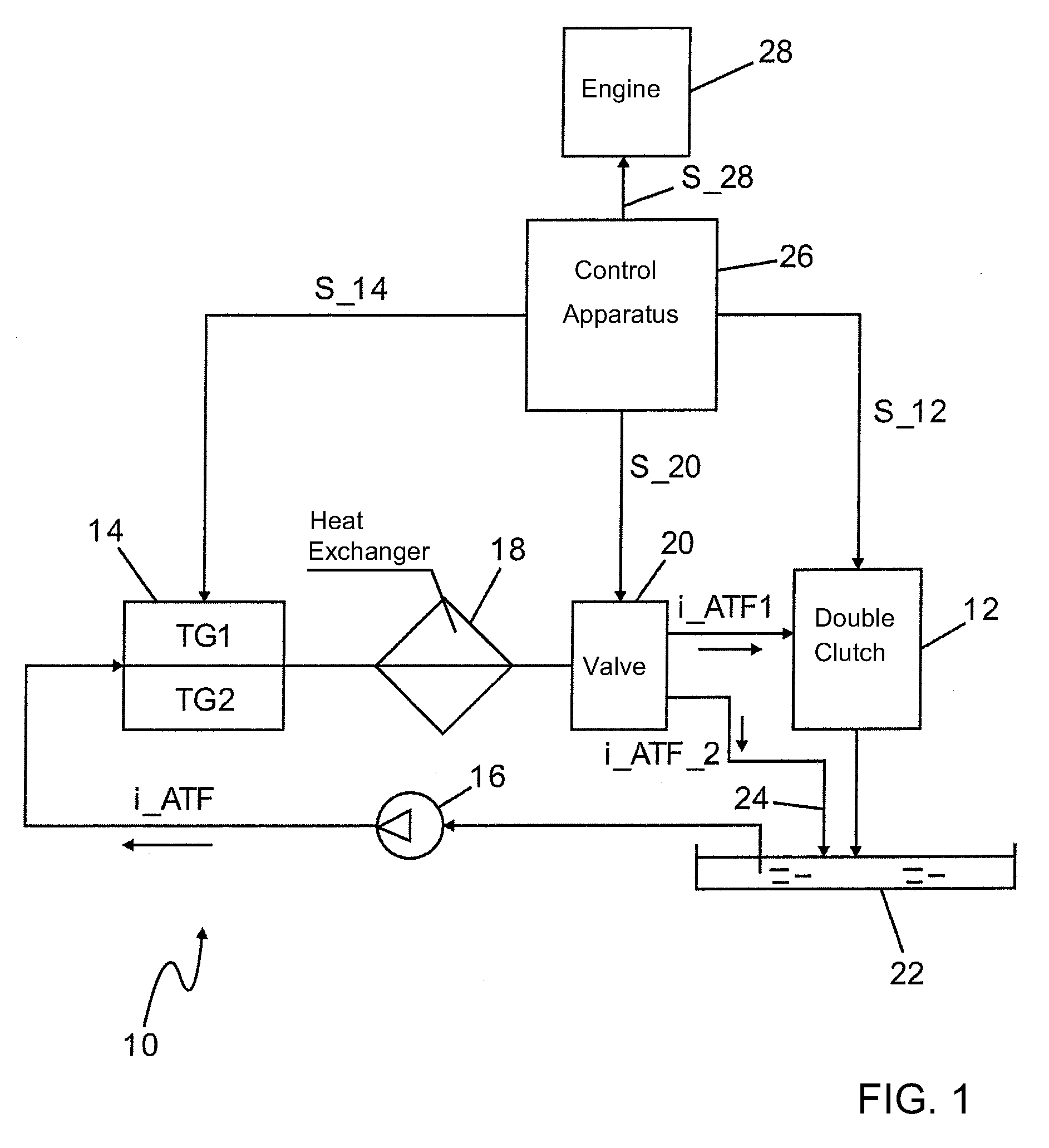
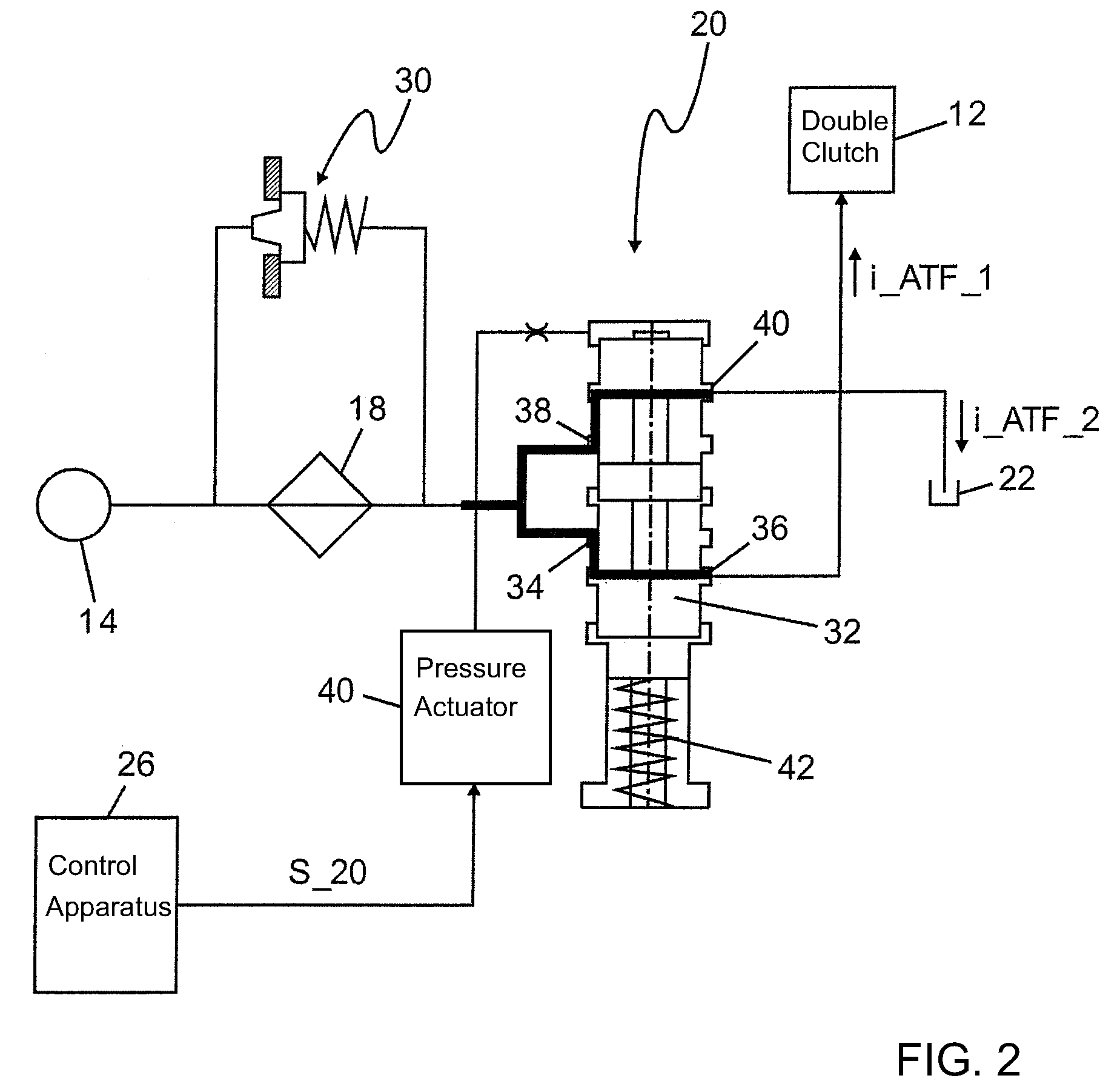
[0023]Referring now to the figures of the drawing in detail and first, particularly, to FIG. 1 thereof, there is shown a hydraulic system 10 of a double clutch 12 of a double clutch transmission as a motor vehicle transmission 14. The hydraulic system 10 has a pump 16 which conveys a hydraulic fluid stream i_ATF to a controllable hydraulic valve 20 via a heat exchanger 18. The pump 16 sucks the hydraulic fluid ATF out of a reservoir 22, puts it under a specific pressure and feeds the hydraulic fluid stream i_ATF into the double clutch transmission 14 which has two part transmissions TG1, TG2. In the double clutch transmission 14, the hydraulic fluid ATF serves for lubrication, cooling and control. Control takes place in that the pressure of the hydraulic fluid is utilized for the actuation of gear actuators, by which step-up ratios within the part transmissions are changed.

[0024]After emerging from the double clutch transmission 14, the hydraulic fluid stream i_ATF is routed through...


PUM


Abstract

A hydraulic system for a clutch has a pump conveying a hydraulic fluid stream via a heat exchanger to a controllable hydraulic valve which divides the hydraulic fluid stream into a first part stream and a second part stream. The first part stream flows to a reservoir via friction linings of the clutch and the second part stream flows to the reservoir via a hydraulic path bypassing the friction linings. The hydraulic system is set up for upgrading a cooling of the clutch by increasing the first part stream at the expense of the second part stream and for reducing the cooling of the clutch by increasing the second part stream. The system is set up for temporarily upgrading the cooling of the clutch in the event of a changeover of torque transfer from transfer via a first part transmission to transfer via a second part transmission of the transmission.

Description

CROSS-REFERENCE TO RELATED APPLICATION[0001]This application claims the priority, under 35 U.S.C. § 119, of German application DE 10 2008 006 165.4, filed Jan. 26, 2008; the prior application is herewith incorporated by reference in its entirety.BACKGROUND OF THE INVENTIONField of the Invention[0002]The invention relates to a hydraulic system of a clutch of a motor vehicle transmission.[0003]Such a hydraulic system is known from published, non-prosecuted German patent application DE 10 2005 013 137 A1. It has a pump which conveys a hydraulic fluid stream to a controllable hydraulic valve via a heat exchanger. The hydraulic valve divides the hydraulic fluid stream into a first part stream and a second part stream. The first part stream flows to a reservoir via friction linings of the clutch, and the second part stream flows to the reservoir via a hydraulic path bypassing the friction linings. The known hydraulic system is set up for upgrading a cooling of the clutch by increasing the...

Claims


Application Information

Patent Timeline
Patent Type & Authority Applications(United States)
IPC IPC(8): F16H61/00
CPCF16D25/123F16D48/066F16D2500/1086F16D2500/70448F16D2500/5029F16D2500/50607F16D2500/30806
Inventor NIKO, MICHAELESSER, JOACHIMBAUR, PETERKRUGER, ARNE
Owner DR ING H C F PORSCHE AG
Why Eureka
Try Eureka