Apparatus And Method For Monitoring An Optical Coherent Network

a technology of optical coherent network and apparatus, applied in the direction of transmission monitoring, transmission monitoring/testing/fault-measurement system, electrical apparatus, etc., can solve the problems of polarization-dependent loss of optical communication system, polarization-mode dispersion (pmd), and general change of polarization orientation of generic signal components

Inactive Publication Date: 2012-07-05
ALCATEL LUCENT SAS
View PDF8 Cites 30 Cited by
  • Summary
  • Abstract
  • Description
  • Claims
  • Application Information

AI Technical Summary

Problems solved by technology

The polarization orientations of the generic signal components unfortunately are generally changed by the birefringence of the fiber, and possibly other fiber properties, during the passage of the signal over t

Method used


Image

  • Apparatus And Method For Monitoring An Optical Coherent Network
  • Apparatus And Method For Monitoring An Optical Coherent Network
  • Apparatus And Method For Monitoring An Optical Coherent Network

Examples


Embodiment Construction

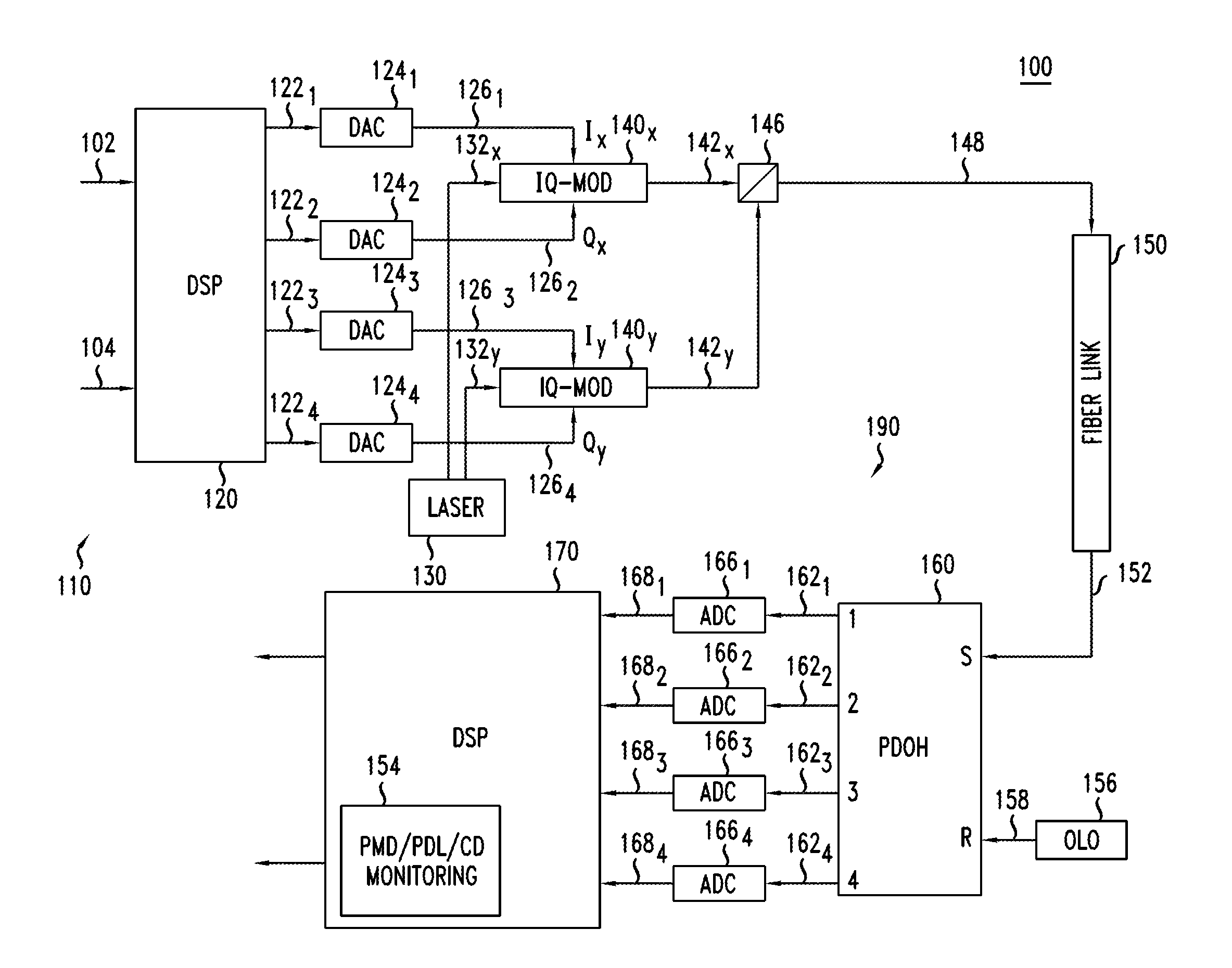
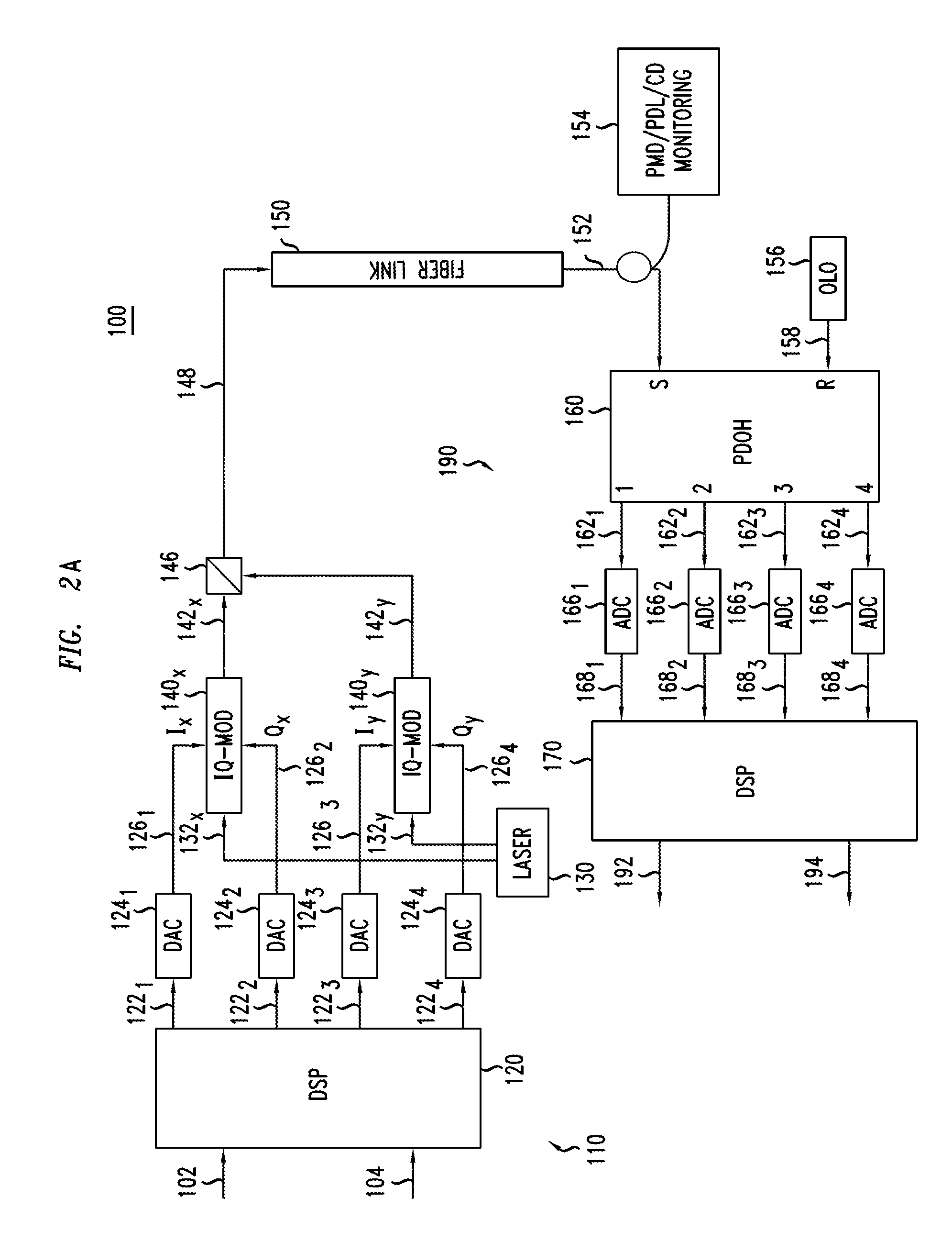
[0024]As mentioned above, the performance of optical networks can be degraded by many factors (i.e., parameters), such as noise, fiber nonlinearities, chromatic dispersion (CD), polarization-mode dispersion (PMD), and polarization-dependent loss (PDL). To manage high capacity, large scale optical networks, it is essential for network operators to monitor these parameters in the optical networks. These parameters can be used for signal impairment assessment, fault localization, routing, et al. For the proper operation of optical networks, network operators not only need to know these parameters of their optical network, but also need to know the range of the parameters that their network can tolerate as well. Therefore, it is important for system vendors to provide such information in their network products.

[0025]PMD is considered as one of the limiting factors in high-speed optical transmission systems. As noted, optical digital coherent detection has recently emerged as a promising...


PUM


Abstract

An example method determines at an optical network monitoring device whether a value for at least one parameter that characterizes an optical signal which traverses a link of an optical coherent network is above a corresponding threshold and sets an alarm indicator when the value is larger than the corresponding threshold. The at least one corresponding parameter is at least one of polarization mode dispersion, polarization dependent loss and chromatic dispersion. An example method may obtains the optical signal from the link of the coherent optical network and determines the value for the at least one parameter, which may entail calculating the value based on the optical signal and filter coefficients of a filter that can be utilized to compensate the optical signal. In another embodiment, the value for the at least one parameter is received from a monitoring unit that determined the value from the optical signal

Description

FIELD OF INVENTION[0001]This invention relates to monitoring for an optical network, and in particular to apparatuses and methods for monitoring for an optical coherent network.DESCRIPTION OF RELATED ART[0002]As is well known, an optical signal may have two orthogonal polarization states, each of which may have different properties. Sometimes such polarization states are intentionally introduced, such as in creating a polarization-multiplexed signal in which the two orthogonal polarization states of the optical carrier are arranged so that each carries different data in order to double the spectral efficiency. Such a polarization-multiplexed signal has two so-called “generic” polarization components, each of which carries a single data modulation. Note that by a generic polarization component it is generally intended the signal at the point at which the modulation of that polarization component is completed. It should be appreciated that each generic polarization component may initi...

Claims


Application Information

Patent Timeline
IPC IPC(8): H04B10/08H04B17/00
CPCH04B10/07951H04B10/0793
Inventor XIE, CHONGJINTKACH, ROBERT WILLIAM
Owner ALCATEL LUCENT SAS
Why Eureka
Try Eureka