Bragg grating with new sampling structure for compensating dispersion and polarization mode dispersion

A grating and grating period technology, applied in the direction of eliminating distortion/dispersion, optics, optical fiber transmission, etc., can solve problems such as complex structure, high control precision requirements, and high price, so as to reduce manufacturing costs, realize precise control, and facilitate precise control Effect

Inactive Publication Date: 2003-08-06
TSINGHUA UNIV +1
View PDF0 Cites 29 Cited by
  • Summary
  • Abstract
  • Description
  • Claims
  • Application Information

AI Technical Summary

Problems solved by technology

[0014] The purpose of the present invention is to solve the problems that type I chirp requires complex and expensive phase templates, requires high control precision in the manufacturing process, or increases packaging complexity, while linear type II chirp is difficult to be used alone for dispersion Compensation and other issues

Method used


Image

  • Bragg grating with new sampling structure for compensating dispersion and polarization mode dispersion
  • Bragg grating with new sampling structure for compensating dispersion and polarization mode dispersion
  • Bragg grating with new sampling structure for compensating dispersion and polarization mode dispersion

Examples


Embodiment Construction

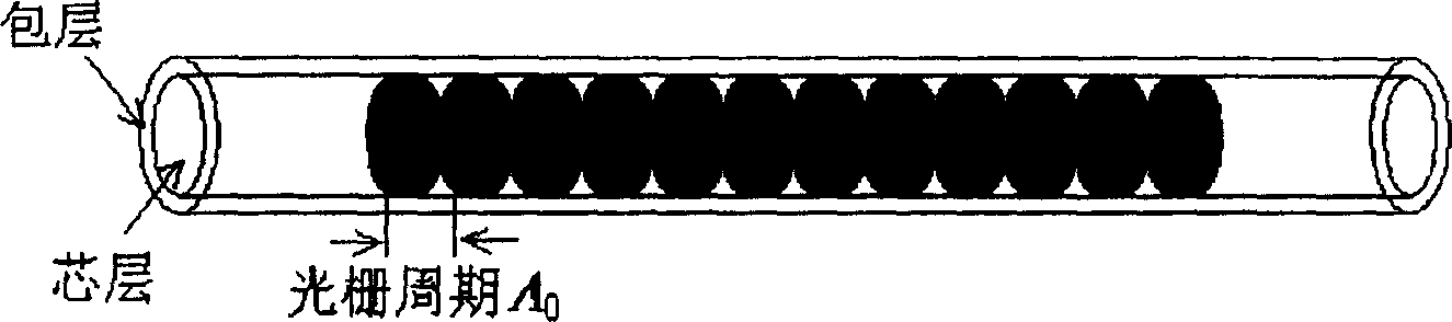
[0040] Figure 8a describe a Bragg grating with a nonlinear type II chirped sampling structure,

[0041] The basic idea of ​​implementing the present invention is to determine the sampling structure F(z) in formula (5) according to the actually required group delay response spectrum. It can be seen from the above formula (5) that F(z) is a periodic function F'(z') through the coordinate transformation of the following formula (7-a) z ′ = z + Σ n = 1 ∞ a n z p n + 1 - - - ( 7 - a ) Transformed. F'(z') is a commonly used periodic sampling structure, such as square wav...


PUM


Abstract

This invention provides a reflective Bragg grating used in dispersion compensatino in optical fiber communication which has effective refractive index perturbation expressed indiagram (1) in which z is a coordinate along the grating direction, A is period of grating beginning, delta ndc is a mean value in a grating period of effective refractive index perturbation, delta nac is the amplitude of that fast variable component is an added phase item, in which F(z) is a new sample structure with non-linear type II chirp display in diagram(2), therefore, this invented grating can provide various group time delay respoonse spectrums to compensate the dispersion in a certain reflecting band independent of chirp (type I) caused by the variation along z by delta ndc or diameter, and F(z) sample period is far more larger than the grating period.

Description

technical field [0001] The invention relates to the field of optical fiber communication, in particular to static dispersion compensation, dynamic dispersion compensation and dynamic polarization mode dispersion compensation in optical fiber communication. Background of the invention [0002] In optical fiber communication systems, the carrier of information is a series of light pulses. After a certain distance of transmission, the light pulse will widen, which will degrade the performance of the system and limit the communication capacity. There are many factors that can cause optical pulse broadening, two of which are dispersion and polarization mode dispersion. [0003] The time required for a light wave packet to travel from the sender to the receiver is called the group delay. Due to the dispersion of the optical fiber, the optical wave packets with different center frequencies travel at different speeds in the optical fiber, so their group delays are also different. ...

Claims


Application Information

Patent Timeline
Patent Type & Authority Applications(China)
IPC IPC(8): G02F1/35H04B10/2519
Inventor 冯佳陈向飞李栩辉谢世钟
Owner TSINGHUA UNIV
Why Eureka
Try Eureka