Method of evaluating fiber PMD using polarization optical time domain reflectometry

a technology of optical time domain and fiber pmd, which is applied in the field of optical fibers, can solve the problems of limiting the transmission rate of pulses or the maximum distance of concatenated fiber medium, and achieve the effect of easy identification

Inactive Publication Date: 2005-09-20
CORNING INC
View PDF7 Cites 28 Cited by
  • Summary
  • Abstract
  • Description
  • Claims
  • Application Information

AI Technical Summary

Benefits of technology

[0012]A preferred source for both emitting the pulse radiation and measuring the radiation which is backscattered or reflected back through the fiber is an optical time domain reflectometer (OTDR). While OTDRs have been used to measure a variety of properties of optical fibers, they are most commonly employed to measure fiber attenuation and to identify locations where breaks or discontinuities occur in the fiber. By OTDR as used herein, we mean a device which is capable of sending a light down an optical waveguide fiber and observing the small fraction of light that is scattered back towards the detector. Typical OTDRs can resolve the intensity of radiation backscattered along the length of the fiber. Most of the OTDRs achieve this by sending pulsed radiation into the fiber under test and measuring the backscattered radiation at a given timing. While typical pulse-widths may range from 0.5 meters (5 nanoseconds) to 2000 meters (20 microseconds), the present invention preferably employs pulse widths of between about 5 and 200 ns, more preferably between about 30 and 150 ns, and most preferably between about 50 and 100 ns. Preferably, the OTDR is a polarization OTDR, which is basically an OTDR capable of emitting polarized radiation and analyzing the polarized radiation from backscattered light.
[0013]One preferred method in accordance with the present invention involves identifying regions of lower or higher variability, relative to other regions along the length of the fiber, to thereby identify areas of higher or lower polarization mode dispersion along the length of the fiber. This can be accomplished, for example, by analyzing a sliding window of data within which a standard deviation (preferably in log scale) is calculated over said window, and moving said window of data lengthwise along the length of the fiber to produce information related to the local variation along the length of the fiber. In one such embodiment, when fiber PMD values are above a certain level, the variation of signals (VOS) drops below a predetermined threshold. In such instances the fiber which falls below the predetermined threshold can then be easily identified and rejected. The predetermined threshold can be selected by mapping the variation of signals against actual measured polarization mode dispersion levels for a number of fibers of the same type. In this way, the level of variation of signals may be selected above or below which the optical fiber passes or fails for a given level of PMD.
[0014]The methods and apparatus of the present invention result in a number of advantages over previous methods for measuring PMD. First, using the methods disclosed herein, PMD measurements may be conducted non-destructively and in a distributed manner along the length of the fiber. Consequently, these methods can be used to test both newly manufactured fiber as well as fiber that is already installed in a telecommunications system. The methods described herein have proven to be useful and valid both for spun and unspun fiber products over a large set of testing data. High spatial resolution OTDRs are not needed, beyond what are already available in existing commercial OTDRs. Most importantly, using the methods disclosed herein, the PMD of a fiber can be measured along the length of the fiber without destroying it. Using the methods disclosed herein, fibers greater than 15 km long and even greater than 25 km long have been successfully analyzed for PMD. In fact, using the method disclosed herein, we have successfully evaluated PMD on fiber lengths greater than 50 km.

Problems solved by technology

The pulse spreading from PMD can introduce errors into the data transmission, effectively limiting the transmission rate of the pulses or the maximum distance of the concatenated fiber medium.
However, fibers are subject to random external perturbations that induce mode coupling between different polarization modes.

Method used


Image

  • Method of evaluating fiber PMD using polarization optical time domain reflectometry
  • Method of evaluating fiber PMD using polarization optical time domain reflectometry
  • Method of evaluating fiber PMD using polarization optical time domain reflectometry

Examples


Embodiment Construction

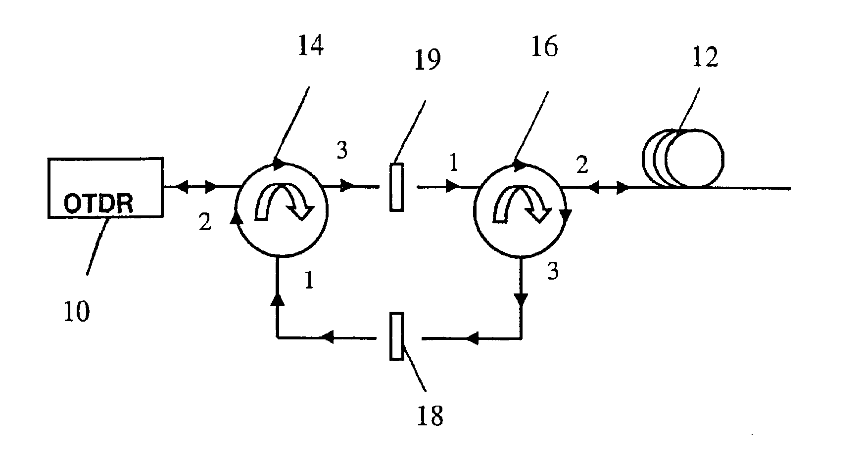
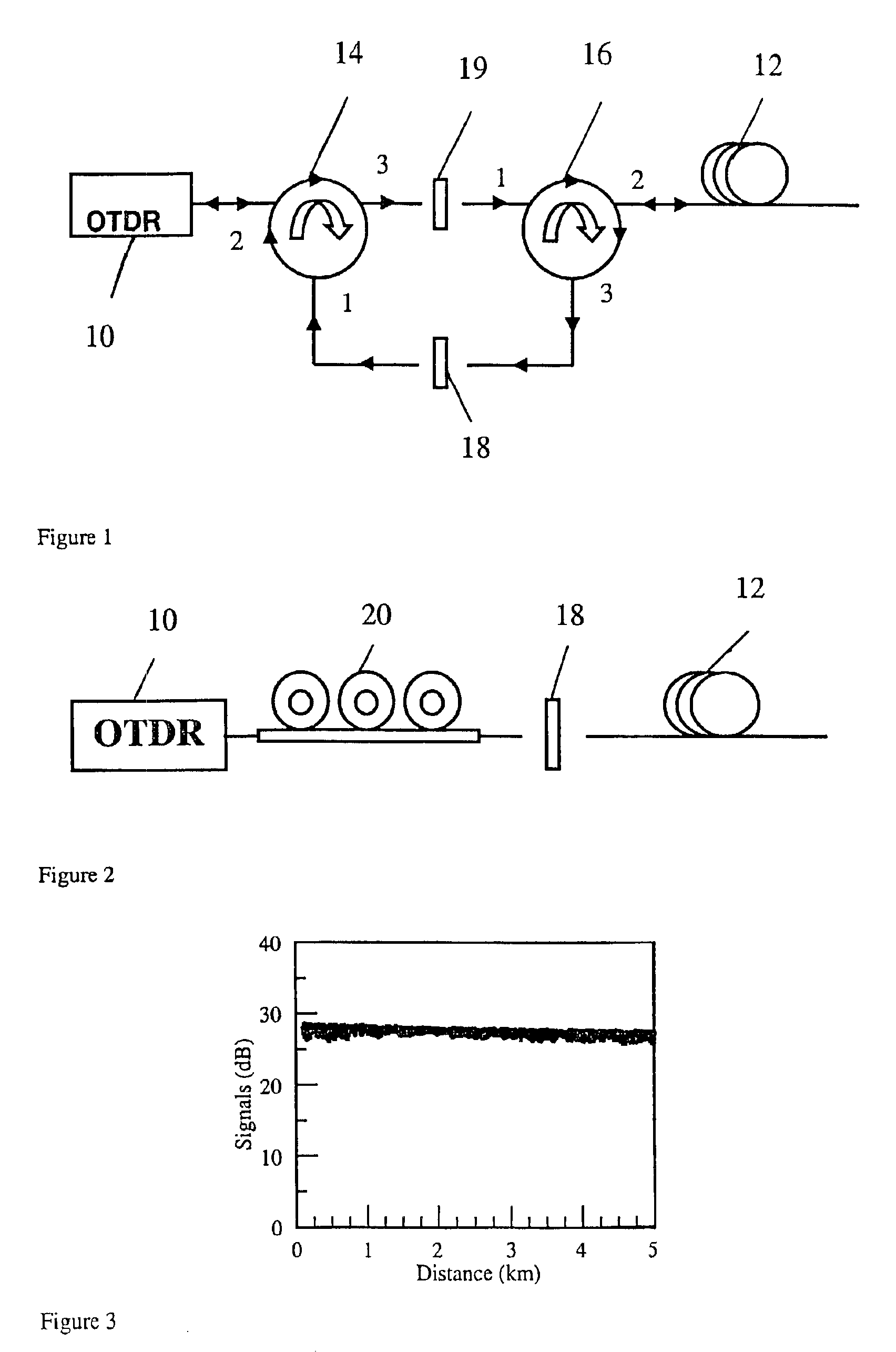
[0031]FIG. 1 illustrates an arrangement suitable for use in practicing the method of the present invention. In FIG. 1, a conventional OTDR 10 apparatus is provided which is capable of sending a pulse of laser light down an optical waveguide fiber. The OTDR is capable of injecting a series of optical pulses into an optical fiber under test. The OTDR can also extract, from the same end of the fiber, light that is scattered back. The intensity of the return pulses is measured and integrated as a function of time, and is plotted as a function of fiber length. OTDR 10 launches a pulsed radiation into the optical fiber 12 which is to be tested for PMD. In the embodiment illustrated in FIG. 1, two optical circulators 14 and 16 and two polarizers 18 and 19 are provided. The optical circulators 14 and 16 are configured to loop the initial pulse of light emitted from the OTDR 10 to the fiber under test. As a result of rayleigh backscattering, some light is back reflected through the fiber bac...


PUM

PropertyMeasurementUnit
lengthaaaaaaaaaa
radiusaaaaaaaaaa
lengthaaaaaaaaaa

Abstract

A method for screening fiber polarization mode dispersion using a polarization optical time domain reflectometer. A pulse radiation is emitted into the fiber under test, and the backscattered radiation is measured by the POTDR and used to obtain a POTDR trace. The POTDR trace is then analyzed to compare the variation of signals along the length of the fiber, the variation in signals relating to the level of PMD along the length of the fiber. Because high levels of PMD correspond to localized levels of low variability, by setting the variability of signal threshold sufficiently low, fibers having unacceptably high localized PMD can be identified and removed.

Description

BACKGROUND OF THE INVENTION[0001]1. Field of the Invention[0002]The present invention relates generally to optical fibers, and particularly to a method for identifying optical fibers which exhibit elevated levels of polarization mode dispersion (PMD).[0003]2. Technical Background[0004]PMD is an important factor in the design of state-of-art fiber optic transmission systems. The effect of PMD in fiber systems is evident when, after propagating a sufficient distance in the network, one digital pulse may spread in the time domain and become indistinguishable from a nearby pulse. The pulse spreading from PMD can introduce errors into the data transmission, effectively limiting the transmission rate of the pulses or the maximum distance of the concatenated fiber medium.[0005]PMD originates from fiber geometric deformation and stress asymmetry. Without external perturbations, the PMD grows linearly at the rate which corresponds to the level of intrinsic fiber birefringence as the fiber le...

Claims


Application Information

Patent Timeline
Patent Type & Authority Patents(United States)
IPC IPC(8): G01M11/00G02F1/01G01J4/00H04B10/00G01J3/447
CPCG01M11/3181G01J3/447
Inventor CHEN, XINHERON, NICOL A.HUNT, TIMOTHY L.MOZDY, ERIC J.STAINER, DARREN A.
Owner CORNING INC
Why Eureka
Try Eureka