Cassette Locking and Ejecting Arrangement

a cassette and locking technology, applied in the field of label printers, can solve the problems of tape and/or ink ribbon not being able to be correctly aligned, tape and/or ink ribbon may vary in height, and achieve the effect of minimizing the movement of the cass

Inactive Publication Date: 2012-07-05
DYMO (BVBA)
View PDF4 Cites 92 Cited by
  • Summary
  • Abstract
  • Description
  • Claims
  • Application Information

AI Technical Summary

Benefits of technology

[0022]Spacing the locking elements apart in this manner allows a cassette to be more firmly held within the cassette-receiving bay and minimizes movement of the cassette within the cassette-receiving bay.
[0080]This arrangement allows a cassette to be more firmly held within the cassette-receiving bay and minimizes movement of the cassette within the cassette-receiving bay. The use of the top of the cassette as the locking mechanism for the smallest cassette maximizes the range of thickness of cassette in the set.

Problems solved by technology

In all the above-described arrangements, a problem exists in that for good quality printing the tape and / or ink ribbon must be correctly aligned with the printhead during printing.
However, in such an arrangement, the height of the cassette may vary if the cassette is not fully pushed downwards into the cassette-receiving bay.
This can lead to misalignment of the tape and / or ink ribbon between the platen roller and print head during printing.
Furthermore, if the cassette moves when printing is taking place, the tape may become creased or folded leading to poor print quality and in a worst case scenario the tape may become snagged in the mechanism which can lead to damage of the tape supply and / or the printer.
The problem is exacerbated in hand held printers which may be moved around during printing.
However the ring cannot rotate under the action of the spring until the cassette is fully inserted.

Method used


Image

  • Cassette Locking and Ejecting Arrangement
  • Cassette Locking and Ejecting Arrangement
  • Cassette Locking and Ejecting Arrangement

Examples


Embodiment Construction

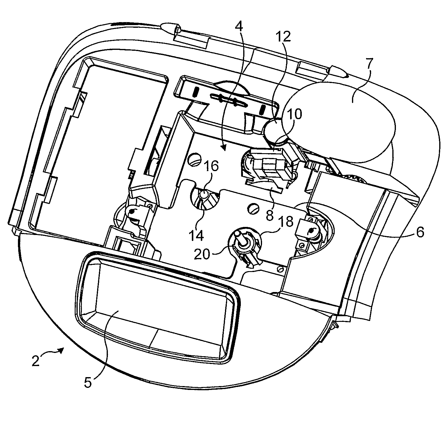
[0123]FIG. 1 shows a top view of a label printer 2 with a lid of the label printer removed to show a cassette-receiving bay 4. The label printer comprises a display 5, a cutter 7 and may also comprise a keyboard (not shown). The cassette-receiving bay 4 is substantially square in cross-section having a base and sidewalls extending from the base to an opening for receiving a cassette therein. A spring biased ejector plate 6 is mounted between the base and the opening of the cassette receiving bay 4. The ejector plate 6 is movable in a downward direction (towards the cassette receiving bay base) and is biased in an upward direction (towards the cassette receiving bay opening) for ejecting a cassette. The ejector plate 6 has an opening 8 therein for receiving a printhead 10 which cooperates with a platen 12 in the conventional manner. The ejector plate 6 has a further opening 14 therein for receiving a sprocket 16 for cooperation with an ink ribbon spool of a cassette. This ink ribbon ...


PUM


Abstract

A label printer comprising a cassette-receiving bay, the cassette-receiving bay having a base, a top opening opposite the base, and a locking mechanism extending from said base, the locking mechanism having a locking part, the locking part being movable in a first direction and biased in a second direction opposite to the first direction, the locking part having one or more projections such that a force thereon directed towards the base causes the locking part to move in the first direction and wherein said locking part is biased to move in the second direction when the force is removed.

Description

REFERENCE TO RELATED APPLICATIONS[0001]This is a Continuation under 35 USC §120 of U.S. patent application Ser. No. 11 / 658,907, which was the US national phase of international patent application PCT / IB2005 / 002518 having an international filing date of Jul. 29, 2005, and claimed priority to Great Britain Patent Appl. Nos. 0417088.2, filed Jul. 30, 2004, and 0511371.7, filed May 16, 2005.FIELD OF THE INVENTION[0002]The present invention relates to a label printer, and particularly to an arrangement for locking a cassette into a label printer and ejecting it.RELATED TECHNOLOGY[0003]Label printers are known, which use a supply of tape, housed in a cassette, received in the label printer. The tape comprises an image receiving layer and a backing layer which are secured to one another via an adhesive layer. Such label printers include a cutting mechanism for cutting off a portion of the tape after an image has been printed onto the image-receiving layer so that the portion of tape having...

Claims


Application Information

Patent Timeline
Patent Type & Authority Applications(United States)
IPC IPC(8): B41J19/00
CPCB41J3/4075B65C9/1892B41J15/044Y10T70/80
Inventor VANDERMEULEN, KRISVEREECKEN, ERWIN
Owner DYMO (BVBA)
Why Eureka
Try Eureka