Radio communication system, radio base station, and handover control method

a radio communication system and radio base station technology, applied in the field of radio communication system, radio base station, and handover control method, can solve the problems and the handover from the radio base station to the radio relay station becomes useless in most cases, so as to prevent the occurrence of process load and communication delay

Inactive Publication Date: 2012-07-05
KYOCERA CORP
View PDF2 Cites 27 Cited by
  • Summary
  • Abstract
  • Description
  • Claims
  • Application Information

AI Technical Summary

Benefits of technology

[0029]According to the present invention, it is possible to provide a radio communication system, a radio base station, and a handover control method, by which it is possible to prevent the occurrence of a process load and communication delay due to useless handover, in a case where a radio relay station is used.

Problems solved by technology

Therefore, it becomes necessary to perform a handover from the radio relay station to the radio base station immediately after performing a handover from the radio base station to the radio relay station, and as a result, the handover from the radio base station to the radio relay station becomes useless in most cases.
The conventional method thus poses a problem of occurrence of a process load and communication delay due to useless handover.

Method used


Image

  • Radio communication system, radio base station, and handover control method
  • Radio communication system, radio base station, and handover control method
  • Radio communication system, radio base station, and handover control method

Examples


first embodiment

[0050]In the first embodiment, (1) Configuration of radio communication system, (2) Operation of radio communication system, and (3) Operation and effect of first embodiment are explained in this order.

[0051](1) Configuration of Radio Communication System

[0052]First of all, the configuration of a radio communication system according to the first embodiment is explained in the order of (1.1) Entire configuration of radio communication system and (1.2) Detailed configuration of radio communication system.

[0053](1.1) Entire Configuration of Radio Communication System

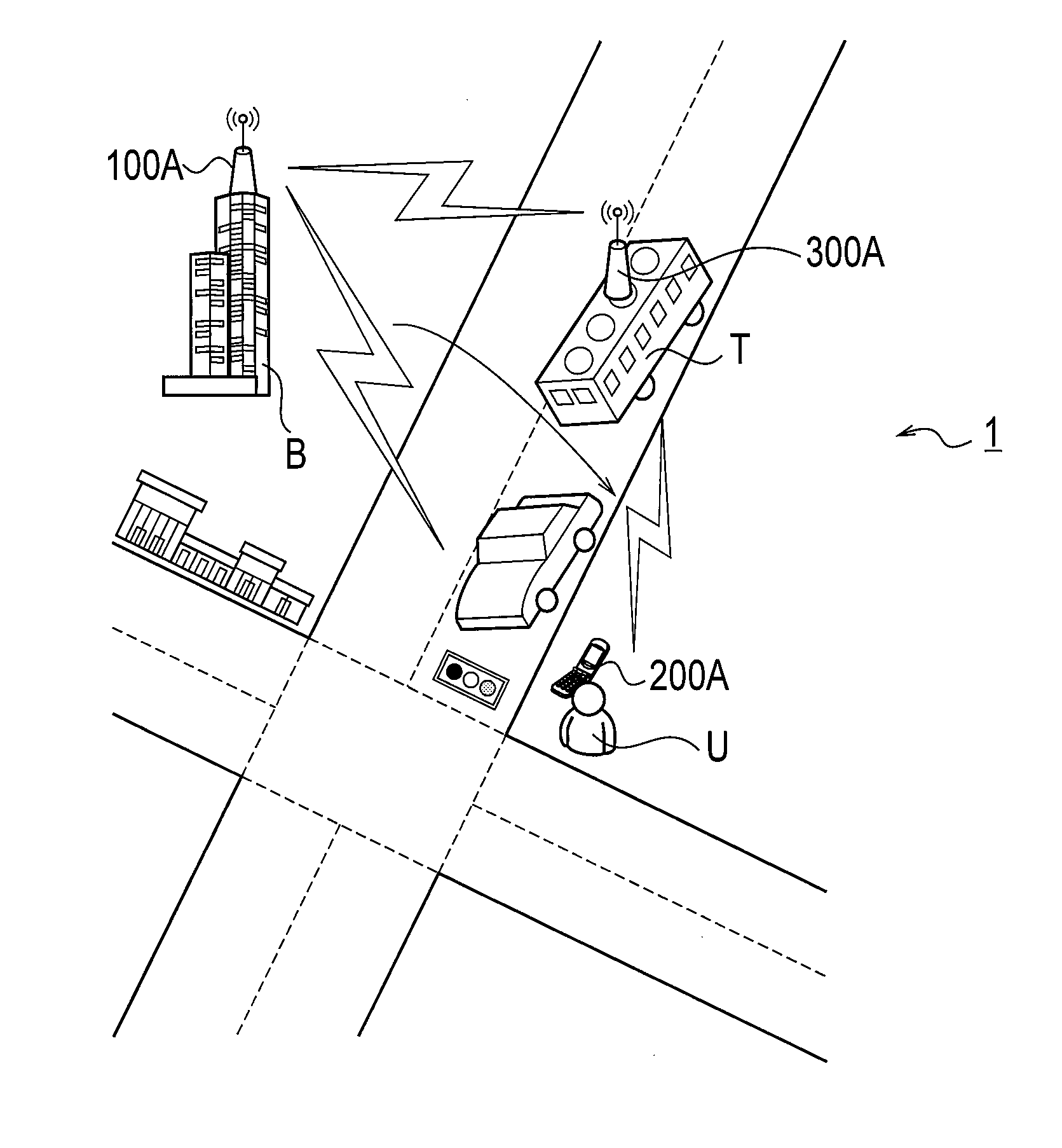
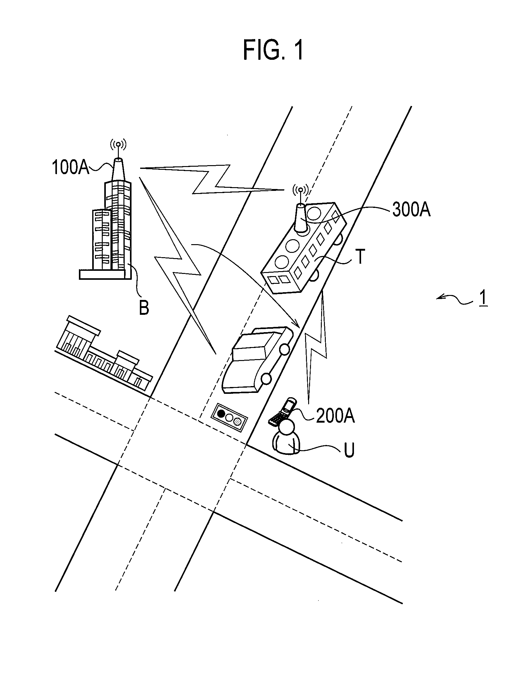
[0054]FIG. 1 is a diagram illustrating the configuration of a radio communication system 1 according to the first embodiment. The radio communication system 1 has a radio base station 100A, a radio terminal 200A, and a relay node 300A (a radio relay station). The radio communication system 1, for example, is configured based on LTE-Advanced which is positioned as a 4th-generation (4G) cellular phone system.

[0055]The radio b...

second embodiment

[0147]Next, a second embodiment of the present invention is explained. Specifically, (1) Configuration of radio communication system, (2) Configuration of radio terminal, (3)

[0148]Configuration of relay node, (4) Detailed operation example of radio communication system, and (5) Operation and effect of second embodiment are explained.

[0149]The second embodiment will be described while focusing mainly on the difference from the first embodiment, and duplicate description will be omitted.

[0150](1) Configuration of Radio Communication System

[0151]FIG. 8 is a diagram illustrating the configuration of a radio communication system according to a second embodiment.

[0152]As shown in FIG. 8, a relay node 300B is installed in the transportation equipment T that a user of a radio terminal 200B can board. The transportation equipment T is not limited to a bus provided as an example in the first embodiment, and may be a train, for example.

[0153]In FIG. 8, a case in which the radio terminal 200B e...

third embodiment

[0189]Next, a third embodiment of the present invention is explained. Specifically, (1) Configuration of radio communication system, (2) Operation of radio communication system, and (3) Operation and effect of third embodiment are explained in this order.

[0190]The third embodiment will be described while focusing mainly on the difference from the first embodiment, and duplicate description will be omitted.

[0191](1) Configuration of Radio Communication System

[0192]FIG. 15 is a diagram illustrating the configuration of the radio communication system 1 according to a third embodiment. As shown in FIG. 15, the radio communication system 1 according to the third embodiment is configured based on LTE-Advanced similar to the first embodiment, and has a radio base station 100D, a radio terminal 200D, a relay node 300D (a radio relay station), and a core network 700.

[0193]In the third embodiment, the core network 700 is configured such that the location information of each of the radio termi...


PUM


Abstract

A radio communication system wherein a radio terminal (200A) and a relay node (300A) are connected to a radio base station (100A), and at least one of the radio terminal (200A) and relay node (300A) can move. The radio base station (100A) controls a handover that is an operation of the radio terminal (200A) to change the connection destination thereof. The radio base station (100A) controls the handover from the radio base station (100A) to the relay node (300A) on the basis of whether a predetermined condition, which indicates that the change in relative distance between the radio terminal (200A) and the relay node (300A) is kept null or small, is satisfied or not.

Description

TECHNICAL FIELD[0001]The present invention relates to a radio communication system to which a relay transmission is applied, a radio base station, and a handover control method.BACKGROUND ART[0002]As the next-generation radio communication system for performing a higher speed communication as compared with the 3rd-generation and 3.5th-generation radio communication systems operated at present, LTE (Long Term Evolution) has been standardized in 3GPP (3rd Generation Partnership Project) which is the standardization body of a radio communication system.[0003]The technical specifications of the LTE have been specified as 3GPP Release 8, and Release 9 which is an upgrade version of Release 8, and LTE Advanced which is a sophisticated version of the LTE, have been currently considered. In LTE Advanced, the adoption of relay transmission using a fixable or movable radio relay station called a relay node is planned (for example, see Non-Patent Document 1).[0004]The radio relay station is a ...

Claims


Application Information

Patent Timeline
Patent Type & Authority Applications(United States)
IPC IPC(8): H04W36/32
CPCH04W84/005H04W36/32
Inventor FUKUTA, NORIYOSHI
Owner KYOCERA CORP
Why Eureka
Try Eureka