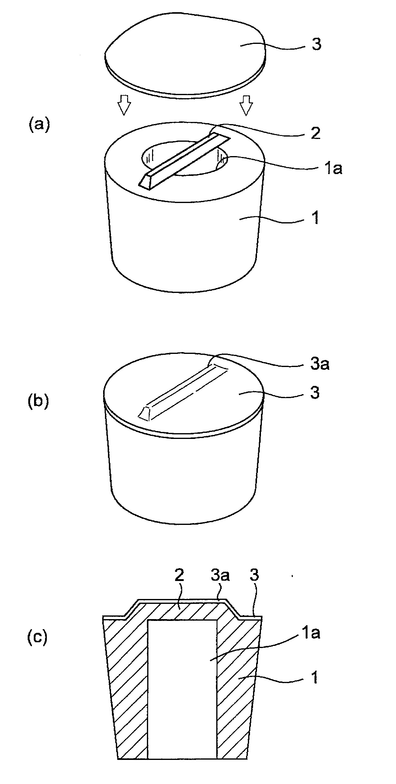
Vent Plug
a technology of vent plugs and plugs, which is applied in the direction of electrical apparatus casings/cabinets/drawers, lighting and heating apparatus, separation processes, etc., can solve the problems of encumbering the case, the difference in pressure between the inside and outside of the case, etc., and achieve excellent effects
- Summary
- Abstract
- Description
- Claims
- Application Information
AI Technical Summary
Benefits of technology
Problems solved by technology
Method used
Image
Examples
embodiment 1
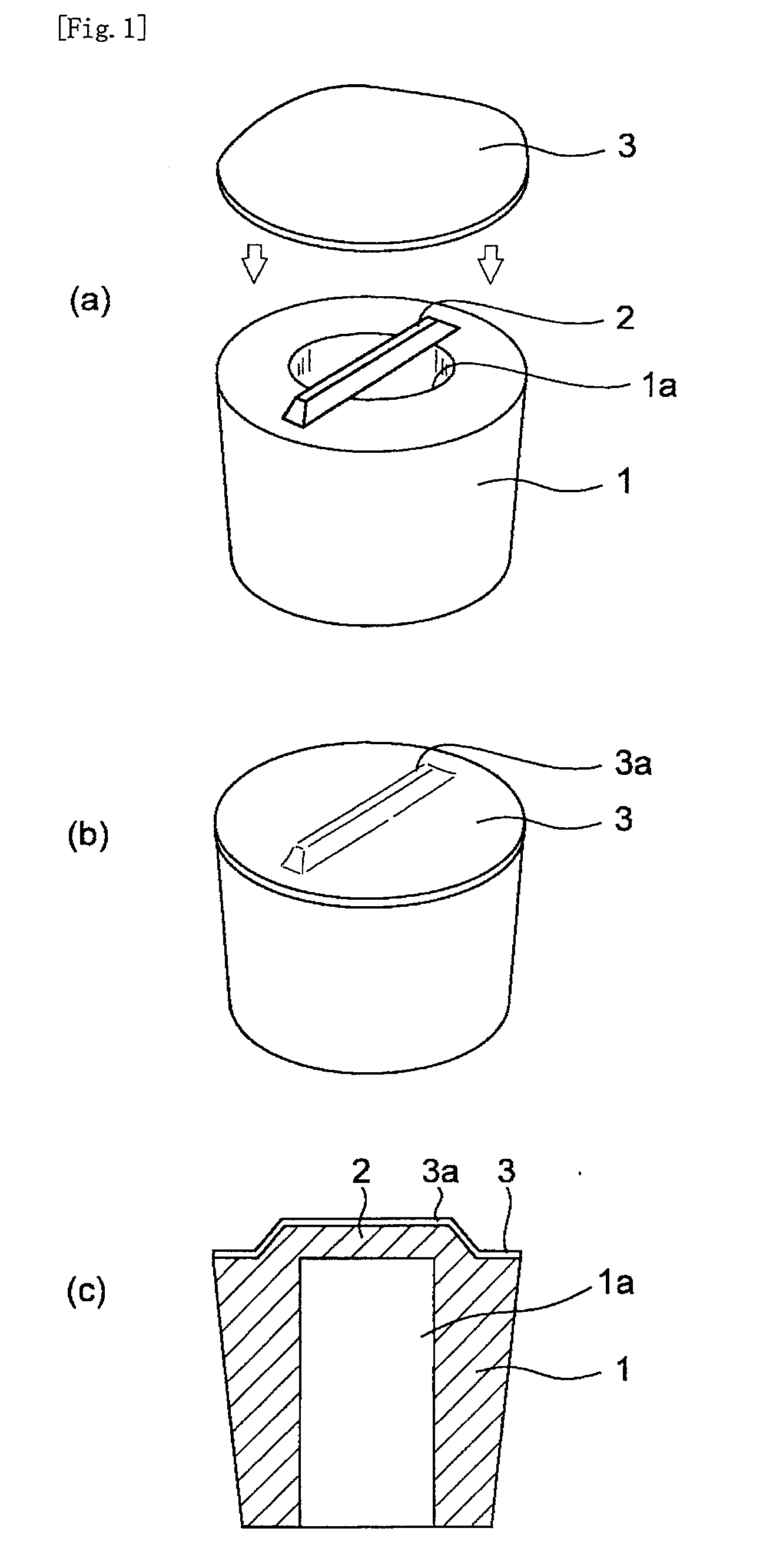
[0037]FIG. 1(a) to (c) show a vent plug according to Embodiment 1 of the present invention: (a) is an exploded view of the vent plug for understanding the internal structure thereof; (b) is a perspective view of the completed vent plug; and (c) is a cross-sectional view of the vent plug. FIG. 1(a) is merely an exploded view as described above, and therefore, the step of attaching an air-permeable membrane 3 to a cylindrical member 1 is not limited to such a form. In this connection, the air-permeable membrane 3 is drawn so as to be thicker than the one actually used.
[0038]In FIG. 1(a) to (c), the cylindrical member 1 having a through-hole 1 a is connected to a support 2 so as to be across the through-hole 1a. Further, the air-permeable membrane 3 is attached so as to cover the cylindrical member 1 and the support 2. As shown in FIG. 1(a) to (c), particularly in (c), the air-permeable membrane 3 is held by the support 2, and the air-permeable membrane 3 has a convex portion 3a that f...
embodiment 2
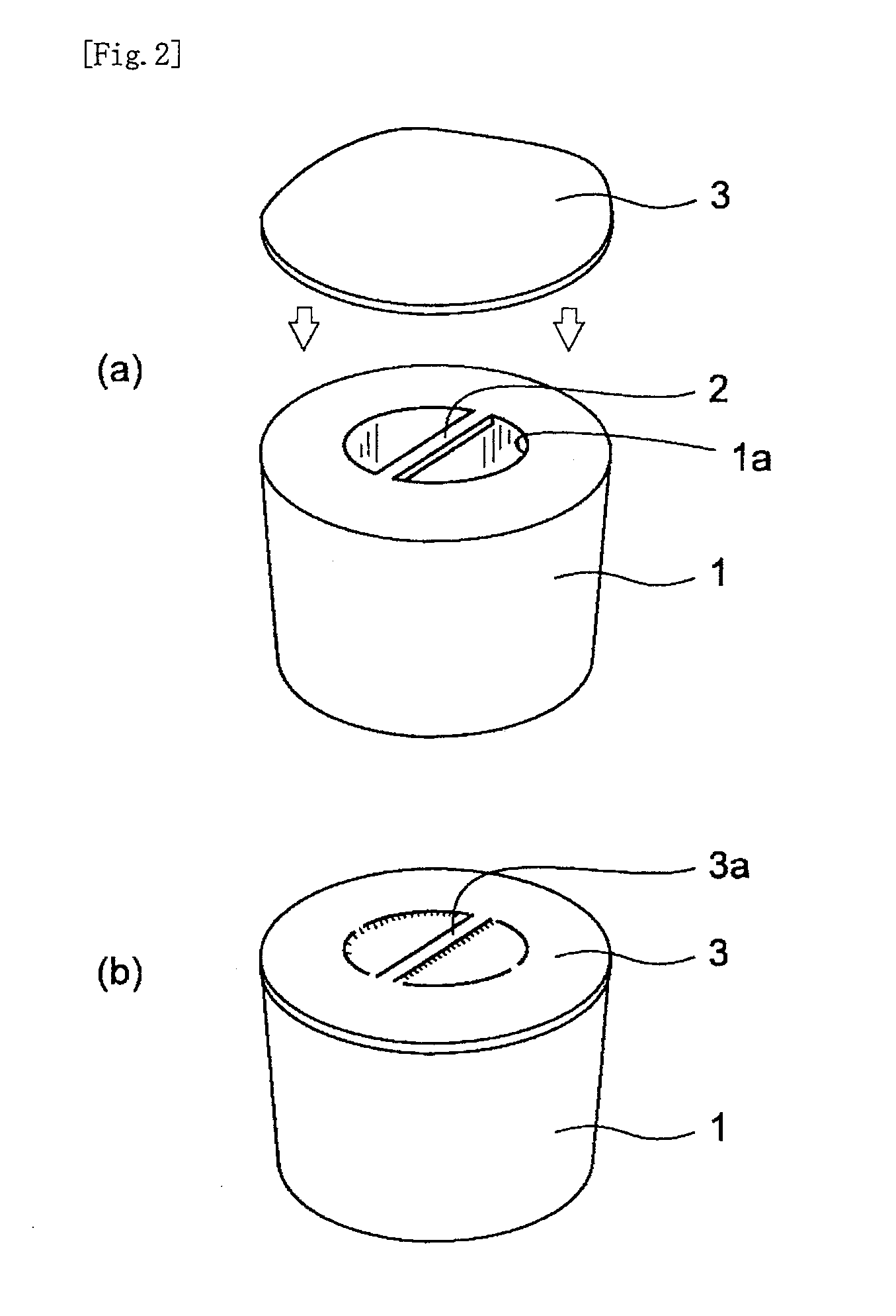
[0045]FIG. 2(a) and (b) show a vent plug according to Embodiment 2 of the present invention: (a) is an exploded view of the vent plug for understanding the internal structure thereof; and (b) is a perspective view of the completed vent plug. The vent plug according to Embodiment 2 is basically similar to the vent plug according to Embodiment 1. In Embodiment 1, however, the form is such that the support 2 is mounted on the cylindrical member 1 of the vent plug, whereas, in Embodiment 2, the support 2 is formed within the through-hole 1a of the cylindrical member 1, and the support 2 is not present at a position higher than the upper surface of the cylindrical member 1. Even in such a form, the air-permeable membrane 3 bends due, for example, to flexure in the portion of the ventilation region of the air-permeable membrane 3, in which portion the support 2 is not present. Thus, the convex portion 3a is formed that follows along the shape of the support 2 in the portion in which the s...
embodiment 3
[0048]FIG. 3 is a perspective view of a vent plug according to Embodiment 3 of the present invention. In the vent plug according to Embodiment 3, the support 2 has a branched structure, and end portions of the support 2 are each connected to the cylindrical member 1. To reduce over a wide range the probability of the air-permeable membrane 3 being damaged, a method may possibly be performed of forming a plurality of rod-like supports 2 as described above. However, when the number of supports 2 is simply increased, the contact between the ventilation region of the air-permeable membrane 3 and the supports 2 may reduce the ventilation efficiency (increase the pressure loss). In contrast, if the support 2 has a branched structure as in the vent plug according to Embodiment 3, the support 2 can be placed at a required portion. This makes it possible to efficiently reduce over a wide range the probability of the air-permeable membrane 3 being damaged, while maintaining a low pressure los...
PUM
| Property | Measurement | Unit |
|---|---|---|
| height | aaaaa | aaaaa |
| temperature | aaaaa | aaaaa |
| pressure | aaaaa | aaaaa |
Abstract
Description
Claims
Application Information
 - R&D
- Intellectual Property
- Life Sciences
- Materials
- Tech Scout
- Unparalleled Data Quality
- Higher Quality Content
- 60% Fewer Hallucinations
Browse by: Latest US Patents, China's latest patents, Technical Efficacy Thesaurus, Application Domain, Technology Topic, Popular Technical Reports.
© 2025 PatSnap. All rights reserved.Legal|Privacy policy|Modern Slavery Act Transparency Statement|Sitemap|About US| Contact US: help@patsnap.com


