
Testing of Optical Cable Using Optical Time Domain Reflectometry

a technology of optical time domain and reflectometry, which is applied in the field of testing of optical fiber connections, can solve problems such as potential faults of optical connectors

Active Publication Date: 2012-07-12
BISON PATENT LICENSING LLC
View PDF3 Cites 65 Cited by
  • Summary
  • Abstract
  • Description
  • Claims
  • Application Information

AI Technical Summary

Problems solved by technology

If the adjusted loss attributable to the optical equipment exceeds the predetermined amount of loss, the method includes identifying the optical connector as potentially faulty.

Method used


Image

  • Testing of Optical Cable Using Optical Time Domain Reflectometry
  • Testing of Optical Cable Using Optical Time Domain Reflectometry
  • Testing of Optical Cable Using Optical Time Domain Reflectometry

Examples


Embodiment Construction

[0025]Various embodiments of the present invention will be described in detail with reference to the drawings, wherein like reference numerals represent like parts and assemblies throughout the several views. Reference to various embodiments does not limit the scope of the invention, which is limited only by the scope of the claims attached hereto. Additionally, any examples set forth in this specification are not intended to be limiting and merely set forth some of the many possible embodiments for the claimed invention.

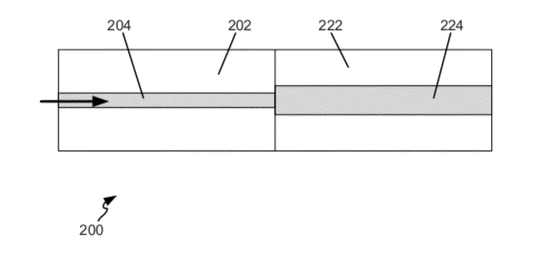
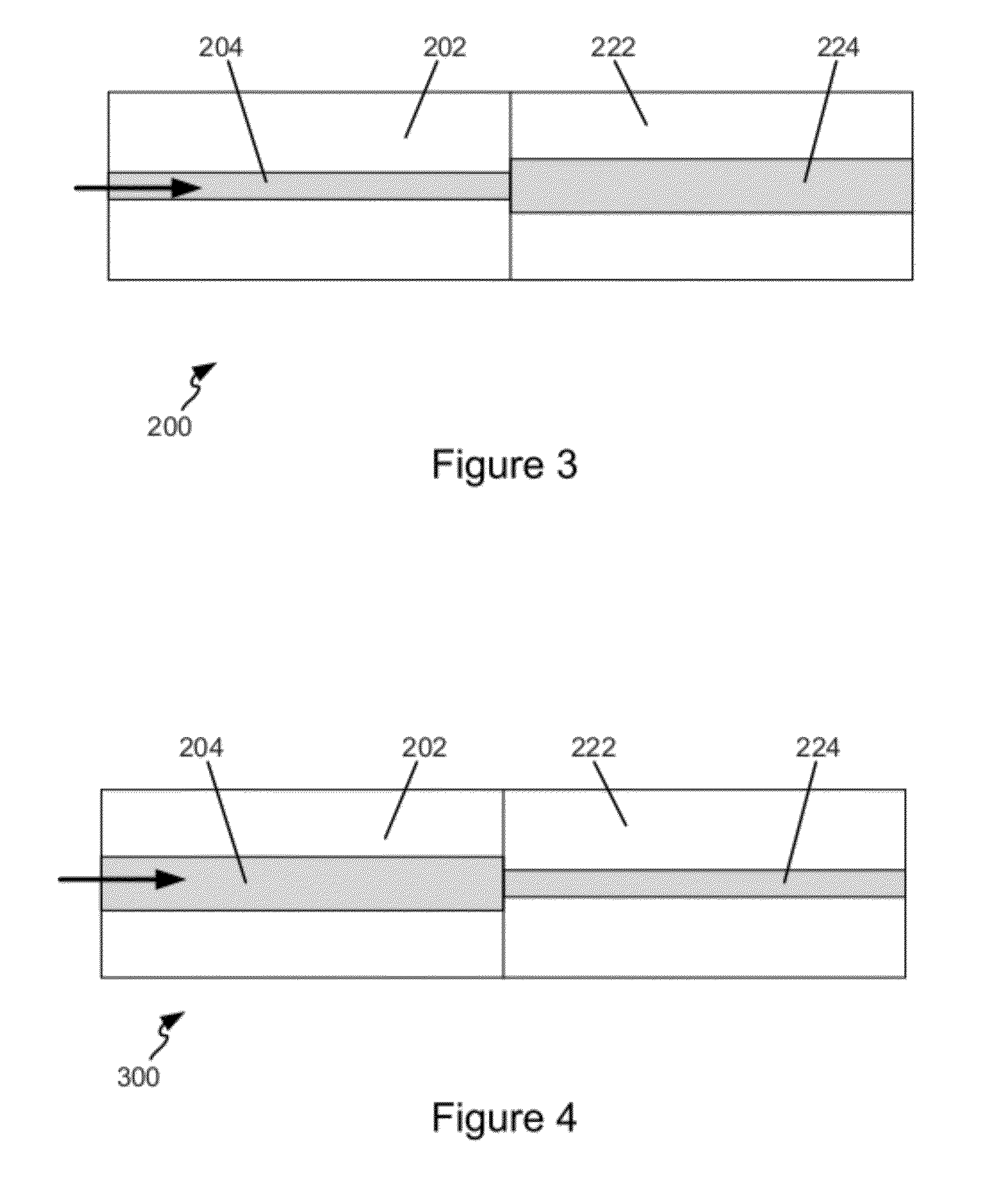
[0026]In general, the present disclosure relates to methods and systems for testing of optical equipment, including the testing of optical connectors included in that equipment to determine if they are faulty. The present disclosure relates to testing methods and test assemblies that can determine whether optical connectors are faulty without requiring each optical assembly to be tested in a bidirectional manner (e.g., detecting a difference in optical power injecte...


PUM


Abstract

Methods for testing optical equipment are disclosed. One method includes connecting an optical time domain reflectometer to optical equipment to be tested, the optical equipment including at least one optical connector. The method includes injecting an optical signal onto the optical equipment from the optical time domain reflectometer, and observing an amount of reflected light at the connector. Based on the observed reflected light, an amount of loss attributable to the optical equipment is determined.

Description

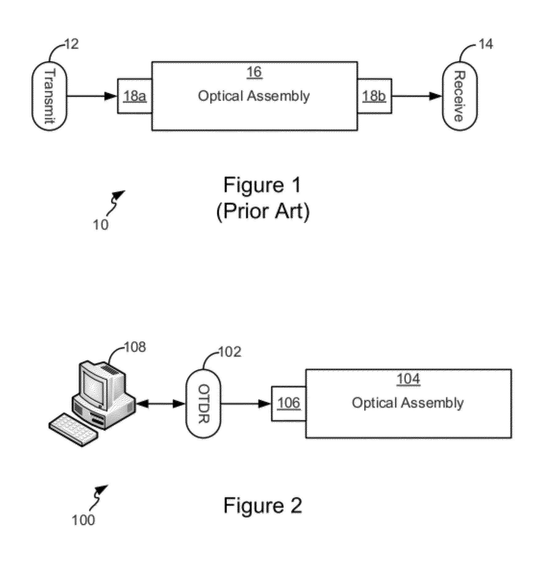
CROSS-REFERENCE TO RELATED APPLICATIONS[0001]The present application claims priority from U.S. Provisional Patent Application No. 61 / 411,771, filed on Nov. 9, 2010, the disclosure of which is hereby incorporated by reference in its entirety.TECHNICAL FIELD[0002]The present disclosure relates generally to testing of optical fiber connections. In particular, the present disclosure relates to testing of optical cable using optical time domain reflectometry.BACKGROUND[0003]Optical components are tested after they are manufactured to determine whether connectors at ends of the components can make a reliable optical connection. A reliable optical connection typically means a connection that has associated with it less than a threshold amount of loss of optical power (e.g., less than a 0.2 dB loss).[0004]Currently, optical testing is performed on an overall throughput loss basis. An example test setup 10 is illustrated in FIG. 1, and includes a transmitter 12 that transmits a signal having...

Claims


Application Information

Patent Timeline
IPC IPC(8): G01N21/00
CPCG01M11/3109
Inventor OTT, MICHAEL JAMES
Owner BISON PATENT LICENSING LLC
Learn More