3-dimensional image display apparatus

a display apparatus and 3d technology, applied in the field of 3d image display apparatus, can solve the problems of eye fatigue, inability to provide monocular depth recognition visual factors, and inability to provide binocular parallax information to a viewer, and achieve the effect of reducing eye fatigu

Active Publication Date: 2012-07-12
SAMSUNG ELECTRONICS CO LTD +1
View PDF9 Cites 88 Cited by
  • Summary
  • Abstract
  • Description
  • Claims
  • Application Information

AI Technical Summary

Benefits of technology

[0022]Therefore, unlike in a holographic stereogram, it is not necessary to newly calculate elements, such as fringe patterns, for each frame. Further, a light field may be reproduced by maintaining a pattern of beam deflectors, which are passive devices, regardless of the images displayed.
[0023]Since 3D display apparatuses according to the examples described herein are based on light field reproduction, the 3D display apparatuses may display more “natural” 3D images, and may help reduce eye fatigue.

Problems solved by technology

However, this mechanism only provides binocular parallax information to a viewer and is unable to provide visual factors for monocular depth recognition, for example, focus adjustment and moving parallax.
Therefore, a 3D image displayed according to this mechanism may present problems such as an “unnatural” image and eye fatigue.
Thus, a relatively large number of projectors is necessary.
Here, since the rotating mirror is moved mechanically, the method generally cannot be applied to a flat panel type display apparatus.
Since directions of light beams are changed through diffraction in the holographic stereogram, a pixel size required on a hologram surface is too small.
Furthermore, when a motion picture is displayed, fringe patterns for each hogel are newly calculated per frame, and thus the amount of required calculations is excessive.

Method used


Image

  • 3-dimensional image display apparatus
  • 3-dimensional image display apparatus
  • 3-dimensional image display apparatus

Examples


Embodiment Construction

[0029]The following detailed description is provided to assist the reader in gaining an understanding of the methods, apparatuses, and / or systems described herein. Accordingly, various changes, modifications, and equivalents of the systems, apparatuses, and / or methods described herein will be suggested to those of ordinary skill in the art. Also, descriptions of well-known functions and constructions may be omitted for increased clarity and conciseness.

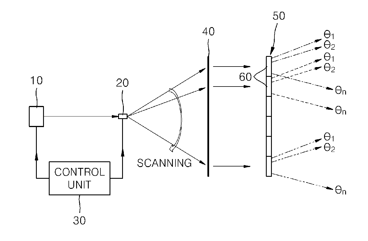
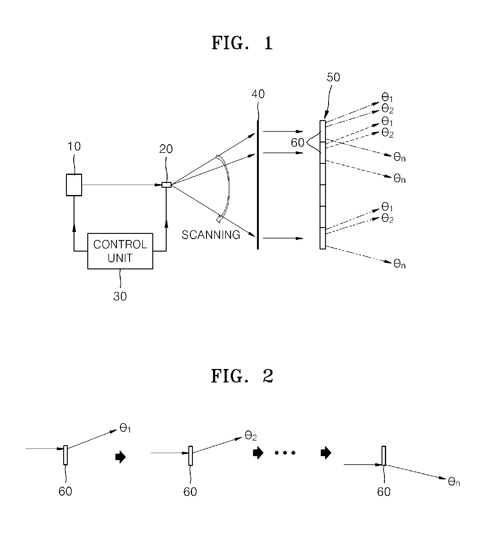
[0030]3-dimensional (3D) display apparatuses according to the examples described herein are provided to resolve problems related to existing 3D display apparatuses that are based on light field reproduction. 3D display apparatuses according to the examples described herein have similar configurations as a holographic stereogram, and thus a plurality of projectors or mechanical movement is not necessary. Furthermore, unlike in a holographic stereogram, 3D display apparatuses according to the examples described herein do not need a new ...


PUM

PropertyMeasurementUnit
angle of incidenceaaaaaaaaaa
image depthaaaaaaaaaa
pixel sizeaaaaaaaaaa

Abstract

Provided is a 3-dimensional (3D) display apparatus including a light source, a beam scanner, and a beam deflector array. The beam scanner scans light emitted by the light source, and the beam deflector array includes a plurality of beam deflectors arranged in an array to reproduce a light field by changing a direction of light rays scanned by the beam scanner.

Description

CROSS-REFERENCE TO RELATED APPLICATIONS[0001]This application claims the benefit of Korean Patent Application No. 10-2011-0002868, filed on Jan. 11, 2011, in the Korean Intellectual Property Office, the disclosure of which is incorporated herein in its entirety by reference for all purposes.BACKGROUND[0002]1. Field[0003]The following description relates to a 3-dimensional (3D) image display apparatus, and more particularly, to a 3D image display apparatus for displaying 3D images by applying a light field mechanism.[0004]2. Description of the Related Art[0005]Commercial 3D display apparatuses typically employ a mechanism in which an image depth is formed by displaying different images to each of the eyes of a viewer. However, this mechanism only provides binocular parallax information to a viewer and is unable to provide visual factors for monocular depth recognition, for example, focus adjustment and moving parallax. Therefore, a 3D image displayed according to this mechanism may p...

Claims


Application Information

Patent Timeline
Patent Type & Authority Applications(United States)
IPC IPC(8): G02F1/29G02B27/42G02B27/10
CPCG02B27/2242G02B30/36G02B27/283G03B21/00H04N13/312H04N13/32H04N13/363H04N13/39
Inventor SONG, HOONLEE, HONG-SEOKPARK, JAE-HYEUNG
Owner SAMSUNG ELECTRONICS CO LTD
Why Eureka
Try Eureka