False eyelashes

a false eyelash and eyelash technology, applied in the field of false eyelashes, can solve the problems of affecting the appearance of the eye, and requiring prudent attention, and achieve the effects of easy handling, good appearance, and good visibility

Inactive Publication Date: 2012-07-19
PROPIA CO LTD
View PDF34 Cites 30 Cited by
  • Summary
  • Abstract
  • Description
  • Claims
  • Application Information

AI Technical Summary

Benefits of technology

[0036]In the false eyelash according to the present invention, since the base is formed into a three-dimensional configuration that contours a curved shape of the eyelid, it may be fitted tightly to the eyelid. Even when the base is formed into substantially a two-dimensional configuration, the base is extremely thin and, therefore, can be fitted tightly to the eyelid along the curved shape of the eyelid. At this time, the hair segments are firmly adhered to the bonding layer in such manner that they remain linearly attached to the base, by which the false eyelash with the hair segments being kept in well aligned state can easily be fitted to the eyelid.
[0037]Further, when it is fitted to the eyelid, because the hair segments are linearly attached to the lower end portion of the base, it can be fitted in such manner that the hair segments are substantially aligned with the own eyelash. Accordingly, the false eyelash could not be distinguished from the own eyelash, providing very good appearance. In addition, the remaining portion of the bonding layer is not visible, providing good visibility.
[0038]The false eyelash according to the present invention provides a planar, wide area for adhesion, and said wide adhesive area is adhered to an upper eyelid, for example. Accordingly, in addition to the fact that the surfaces of the base held by the user are wide, planar, easily-handled surfaces, it is very easy to position the base end portion to align with the lower edge of the upper eyelid when fitting the false eyelash, thereby greatly saving labor and time required for the fitting operation. Further, the adhesive surface is planar and has a wide area for adhesion to the eyelid, which prevent slippage and separation of the false eyelash while in use.

Problems solved by technology

The prior arts use bonding agent for adhesion of false eyelash, which has the risk that the eye could be damaged.
Accordingly, the false eyelash adhering operation should be done with case, which requires prudent attention and take a long time.
This makes it extremely difficult to fit the false eyelash in position, which requires high-level skill.
Even if it is once adhered successfully, it is adhered linearly or spottily only in an extremely small area so that it could be slipped off due to up-and-down movement of the eyelid while in use, which greatly spoils appearance.

Method used


Image

  • False eyelashes
  • False eyelashes
  • False eyelashes

Examples


second embodiment

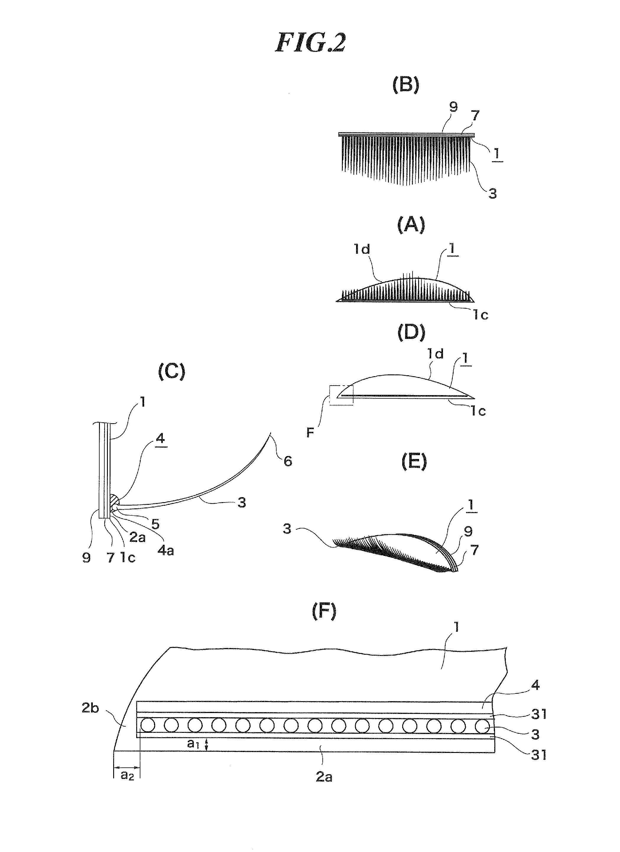
[0057]FIG. 2 shows a false eyelash according to the present invention. A base 1 of this embodiment is formed substantially planar, not customized. Hair segments 3 are adhered to the bonding layer 4 in a state wherein they are connected with each other by linear members 31. The structure excepting these points will be similar to the embodiment of FIG. 1.

[0058]FIG. 3 shows the base 1 used in the false eyelash of FIG. 2. The spaces will be explained here. The spaces 2a, 2b should be somewhat smaller than the diameter of a single hair. More particularly, a distance a1 should preferably be about 0.1-0.6 mm, and a distance a2 should preferably be about 0.1-0.6 mm. The base 1 in this embodiment has length L of about 26 mm, considering that an average eye size i of a Japanese (shown in FIG. 8(A)) is about 30 mm. Its maximum width is about 2.6 mm (WO for a single-edged eyelid, and about 4 mm (W2) for double-edged or internally double-edged eyelid. The base 1 may have various shapes depending...

third embodiment

[0060]The embodiments of FIG. 1 and FIG. 2 will be shipped, after being cut in a factory to a predetermined shape of a false eyelash, whereas the present invention shown in FIG. 5 is of a type wherein it is cut by the user. In this embodiment, the base 1 is cut into a rectangular shape 1M that is larger than a predetermined false eyelash shape. For use, the user should cut by herself the base 1 of the false eyelash along a cutting line shown in FIG. 7. In FIG. 5(A), a reference numeral 1a denotes the base after having been cut. The structure excepting these points will be similar to the embodiment of FIG. 1.

[0061]Regarding the size of various parts of the false eyelash shown in

[0062]FIG. 5, the vertical length of a pre-use base 1 is about 20-30 mm (a) for business use, and about 10-05 mm (b) for personal use where it is cut near to the base end portion 1c. The lateral length (c) is about 10-40 mm in common. The longitudinal size (d) of the hair segment 3 is about 2-12 mm. Each hair ...


PUM


Abstract

A false eyelash that is easily wearable and prevented from slippage and separation while in use includes an extremely thin base, bonding layer formed linearly on a surface of the base, a plurality of hair segments individually and separately adhered to the bonding layer, and an adhesive layer formed on an entire underside of the base. The base is formed into substantially a two-dimensional configuration or three-dimensional configuration that contours a curved shape of an eyelid to which the base is fitted. Since the base is formed into an extremely thin two-dimensional configuration or a three-dimensional configuration that contours a curved shape of the eyelid, it may be fitted tightly to the eyelid. The hair segments are firmly adhered to the bonding layer such that they remain linearly attached to the base, by which the false eyelash with the well-aligned hair segments can easily be fitted to the eyelid.

Description

TECHNICAL FIELD[0001]The present invention relates to a false eyelash.BACKGROUND ART[0002]As shown in FIG. 12, the prior art false eyelash 103 comprises an extremely thin linear base 101 having approximately 0.5 mm width and artificial eyelash transplanted onto the base, which is attached with bonding agent to an eyelid just above an eyelash 122. Another type prior art is, as shown in FIG. 13, adhered spottedly by using tweezers, for example, to a removed part of an eyelash 122 or to other reinforcing sites, at usually one or several points.PRIOR ARTSPatent Documents[0003]Patent Document 1: JP1974-044493A(U)[0004]Patent Document 2: JP2008-231632ASUMMARY OF INVENTIONProblems to be Solved[0005]The prior arts use bonding agent for adhesion of false eyelash, which has the risk that the eye could be damaged. Accordingly, the false eyelash adhering operation should be done with case, which requires prudent attention and take a long time. In some case, the false eyelash is used even though...

Claims


Application Information

Patent Timeline
Patent Type & Authority Applications(United States)
IPC IPC(8): A41G5/02
CPCA41G5/02
Inventor HOCHI, HIROSHIWATANABE, MITSUHIRO
Owner PROPIA CO LTD
Why Eureka
Try Eureka