Low-Power Magnetic Slope Detecting Circuit

a detection circuit and low-power technology, applied in the field of low-power magnetic slope detection circuits, can solve problems such as difficulty in achieving high measurement accuracy

Active Publication Date: 2012-07-19
INFINEON TECH AG
View PDF7 Cites 42 Cited by
  • Summary
  • Abstract
  • Description
  • Claims
  • Application Information

AI Technical Summary

Problems solved by technology

However, in many applications it is difficult to achieve a high measurement accuracy without consuming a large curre

Method used


Image

  • Low-Power Magnetic Slope Detecting Circuit
  • Low-Power Magnetic Slope Detecting Circuit
  • Low-Power Magnetic Slope Detecting Circuit

Examples


Embodiment Construction

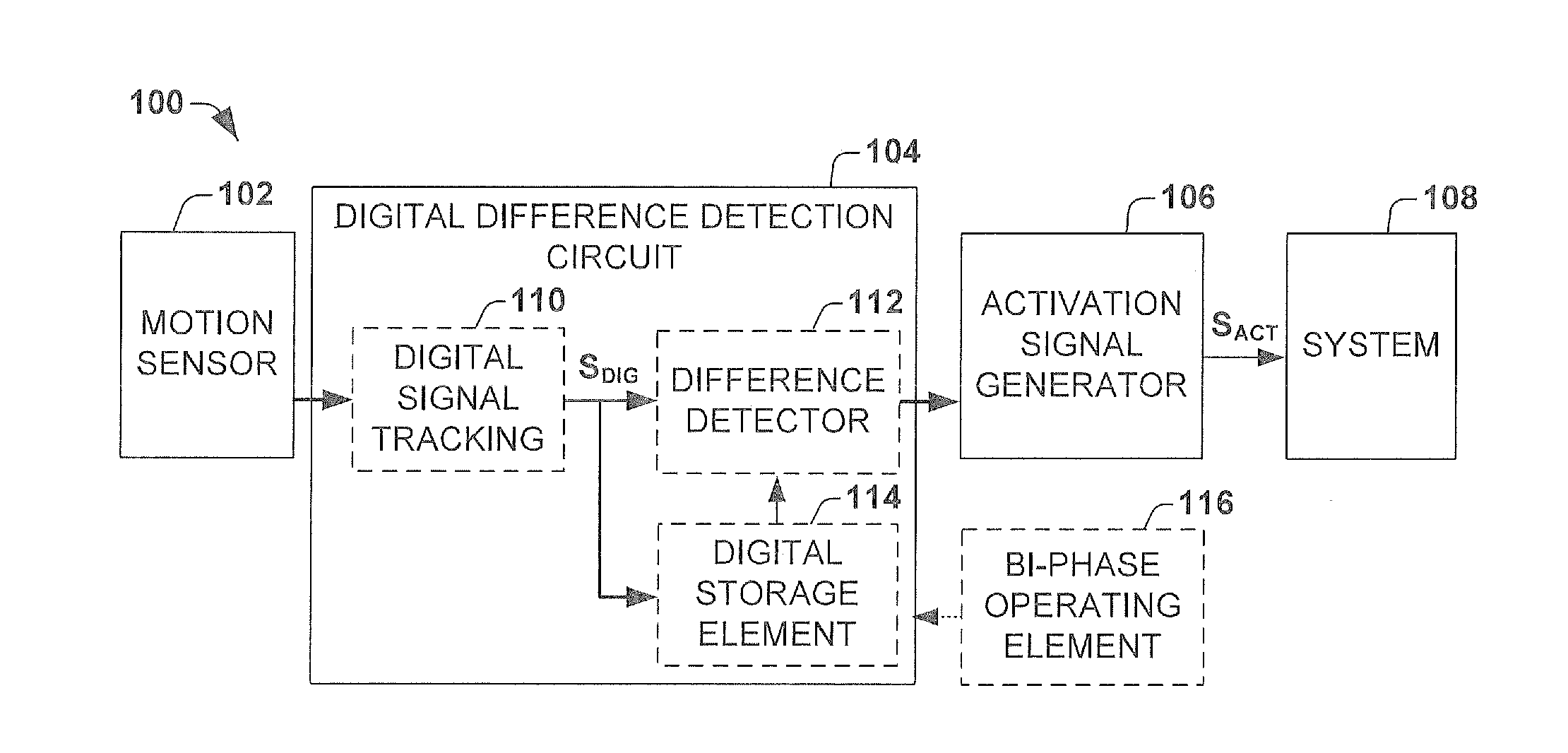
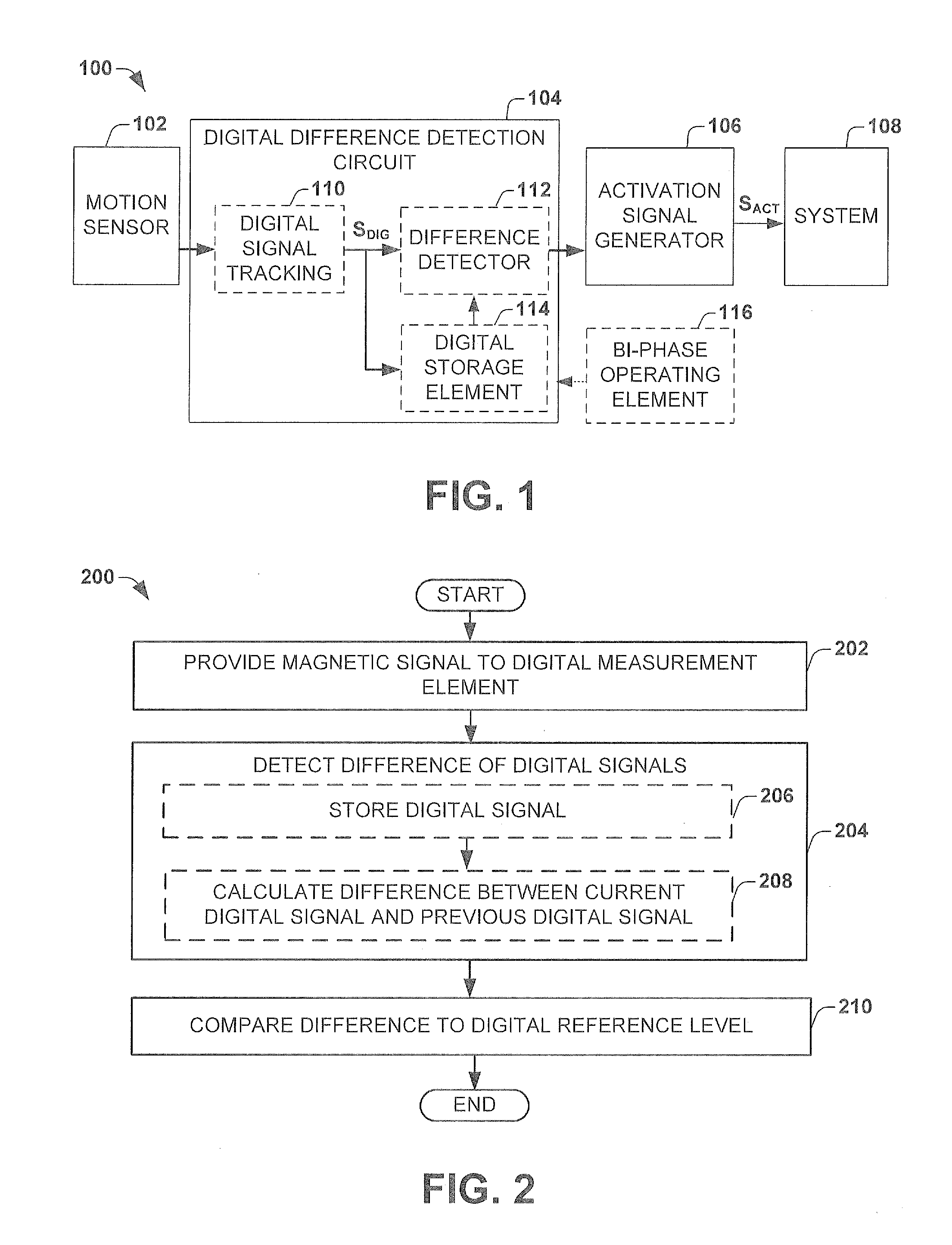
[0014]The present invention will now be described with reference to the attached drawing figures, wherein like reference numerals are used to refer to like elements throughout, and wherein the illustrated structures and devices are not necessarily drawn to scale.

[0015]As provided herein, the term “difference” denotes the absolute magnitude of a change (i.e., a positive value). Therefore, the term difference encompasses both a change from a first lower value to a second higher value (a positive change) and a change from a first higher value to a second lower value (a negative change). Accordingly, as provided herein a difference in a digital signal may comprise an absolute value of a positive difference and / or a negative difference, wherein the differences (absolute values) of either be larger than a positive valued digital reference value so long as the magnitude of the difference is larger than the positive digital reference value.

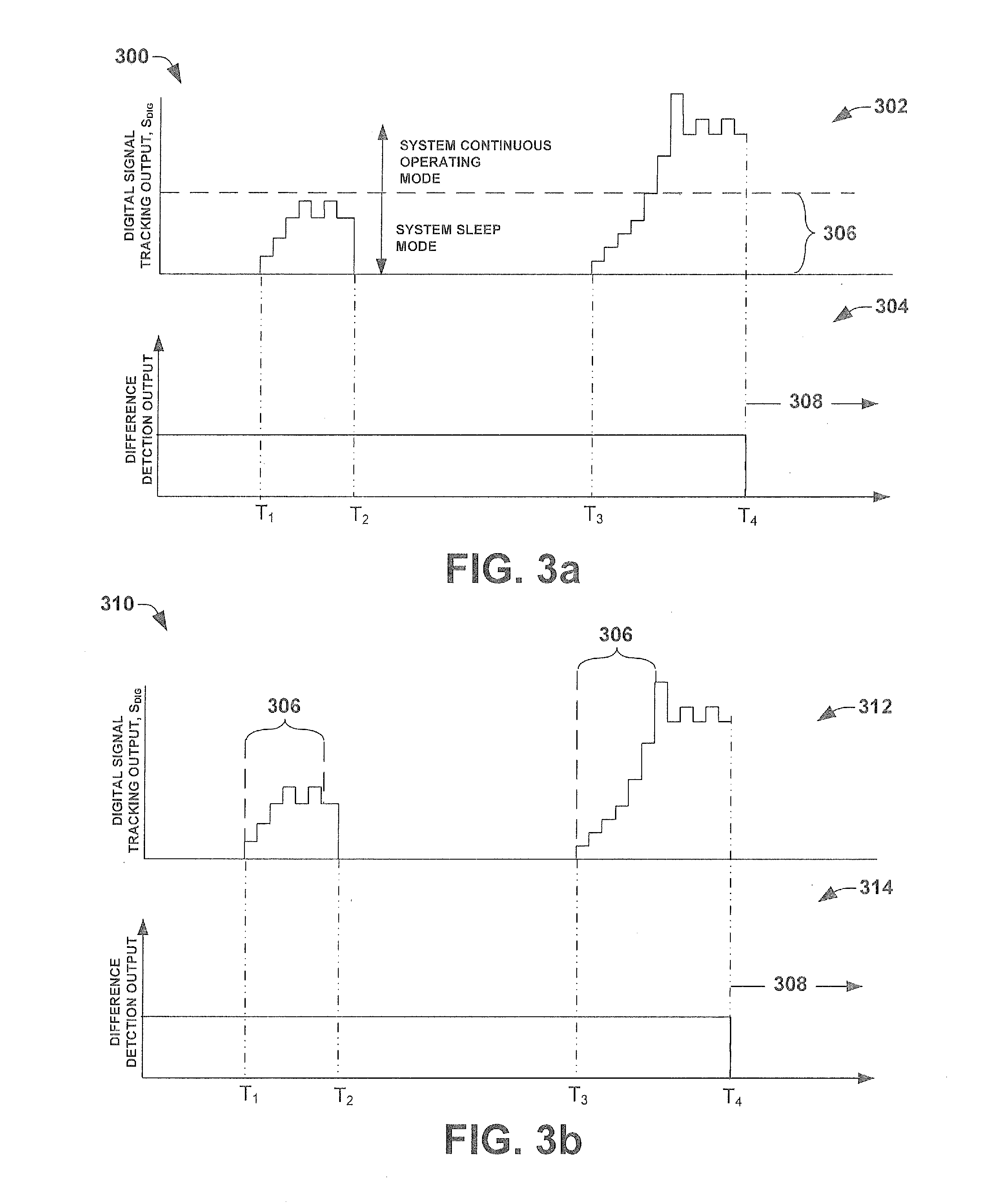
[0016]To lower power consumption, a system may be c...


PUM


Abstract

One embodiment of the present invention relates to a method and apparatus to perform a low power activation of a system by measuring the slope of a digital signal corresponding to a motion sensor measurement value. In one embodiment, a low power activation circuit is coupled to magnetic motion sensor configured to output a magnetic signal proportional to a measured magnetic field. The low power activation circuit may comprise a digital tracking circuit configured to provide a digital signal that tracks the magnetic field and a difference detector configured to detect a difference between a current digital signal and a prior digital signal stored in a digital storage means. If the detected difference is larger than a digital reference level, an activation signal is output to awaken a system from a sleep mode.

Description

BACKGROUND OF THE INVENTION[0001]In many modern day electronic applications, low power consumption is an important design consideration. To reduce the power consumption of an electronic device / system (e.g., a microprocessor), the device / system may be switched from a low power functionally inactive “sleep” mode to a functionally active continuously operating mode. Activating a device / system from sleep mode to a continuous operating mode may be done with accurate contactless measurements. For example, in automotive applications many systems (e.g., headlights, gear shift, etc.) may be configured to operate based upon sensors configured to detect a state of operation (e.g., off, on, parking lights, high beams). However, in many applications it is difficult to achieve a high measurement accuracy without consuming a large current to achieve the contactless measurement (e.g., across a Hall plate or anisotropic magnetoresistance (AMR) sensor).BRIEF DESCRIPTION OF THE DRAWINGS[0002]FIG. 1 il...

Claims


Application Information

Patent Timeline
IPC IPC(8): H03K5/00G01R33/02H02H3/20G01R25/00
CPCG01P3/489H03K17/94G01R33/0029G01P13/00H03K5/2472H03K17/9517G01D5/142G01R17/02G01R19/0092
Inventor MOTZ, MARIO
Owner INFINEON TECH AG
Why Eureka
Try Eureka