Multi-positional stand and under cabinet mount for a tablet computer

a tablet computer and tabletop technology, applied in the direction of machine supports, electric apparatus casings/cabinets/drawers, instruments, etc., can solve the problems of not being portable, not allowing for screen rotation by touch, and not allowing the stand to be mounted to the bottom of a shelf or cabin

Inactive Publication Date: 2012-07-19
AUTUMN HORIZONS
View PDF3 Cites 58 Cited by
  • Summary
  • Abstract
  • Description
  • Claims
  • Application Information

AI Technical Summary

Benefits of technology

[0006]The Multi-positional Stand and Under Cabinet Mount for a Tablet Computer, currently described herein, is developed to meet the need for a stand that can sit on a flat, horizontal surface and allows for a tablet computer to be temporarily attached to it allowing full rotation of the tablet computer about an axis running centered on the face of and perpendicular to its face, therefore, allowing the tablet computer to be in both a portrait (vertical) and a landscape (horizontal) position, and in every position in between. Furthermore, the stand has been designed to mount (upside down) to the bottom of a kitchen cabinet so that the attached tablet computer can be viewed, touched and manipulated in a kitchen without using counter space. Furthermore, while mounted to the bottom of a cabinet the stand has been designed to tilt back and up so that it is parallel with and close to the bottom surface of the cabinet so that counter space directly below the stand is fully accessible by the user. Furthermore, the stand has been designed to mount to the bottom (or top) of a shelf or other fixed horizontal surface so that the attached tablet computer can be viewed, touched and manipulated in an office or in a workroom without obstructing desk or work table space below. When useful, the stand and mount can also be attached to the side of a cabinet, or to a wall.
[0008]The bottom portion of the hinge member is furthermore pivotally attached to the front of the base member. The angular position of the hinge member and base member can be locked or unlocked in any one of an infinite number of angular positions within a range by the manual rotation of 2 cam-actuated handles. The cam-actuated handles are designed so that when they are manually pivoted and point away from the base member the cam surfaces on the cam-actuated handles squeeze the surfaces of the hinge member and base member together and therefore lock the position. The invention provides for lock washers between the contacting surfaces of the hinge member and the base member to help create more friction and a stronger lock so that the tablet computer, being attached to the stand, can be poked with a user's fingers without causing a change in the angular position of the hinge member with respect to the base member. Furthermore, the cam-actuated handles are designed so that when they are manually pivoted towards (parallel to) the base member the cam surfaces on the cam-actuated handles move away from the surfaces of the hinge member and base member and allow for the hinge member and base member to freely pivot with respect to each other.
[0009]The invention provides for a hinge pin and two partially-threaded locking pins that fix the distance between the two cam-actuated handles about their centers of pivot. The hinge pin goes through holes in the sides of the bottom ends of the hinge member and through a hole in the sides of the front portion of the base member. The cam-actuated handles provide the secondary purpose of stabilizing the stand when they are extended and in a locked position. The invention provides for a base mount that has a top edge that can be attached to a flat horizontal or vertical surface with screws, and has a bottom surface to which the underside of the base member can be temporarily attached. The invention provides for a slot to be cut through the central portion of the base member, running top to bottom and orientated depthwise. The invention provides for the base mount to have a hex-head screw affixed to and extending out from its outer surface. The hex head screw can pass through the slot on the base member. The invention provides for the stand to be temporarily attached to the base mount with a threaded attachment knob which threads onto the base mount's hex-head screw, therefore, sandwiching the base member in place. The invention provides for rotation between the bottom surface of the base member and the bottom surface of the base mount about an axis that passes through the length of the hex-head screw so that the screen of the tablet computer can turn sideways when the user is not standing directly in front of the cabinet or shelf under which the stand is attached.

Problems solved by technology

Some of them sit on a horizontal surface and are designed to be portable and collapsible, but don't allow for screen rotation by touch.
Some of these new stands allow the tablet computer to tilt and allow the screen to rotate but do not allow for the stand to be mounted to the bottom of a shelf or cabinet.
Some of these new stands are designed to mount the tablet computer to a fixed vertical surface, such as a wall, or under a horizontal surface, such as a cabinet or shelf, but are not portable.
Some of these new stands can be incrementally tilted backwards or fixed in a specified number of reclined positions, but don't allow the recline angle to be locked in all possible angular positions between fully vertical and fully horizontal.

Method used


Image

  • Multi-positional stand and under cabinet mount for a tablet computer
  • Multi-positional stand and under cabinet mount for a tablet computer
  • Multi-positional stand and under cabinet mount for a tablet computer

Examples


Embodiment Construction

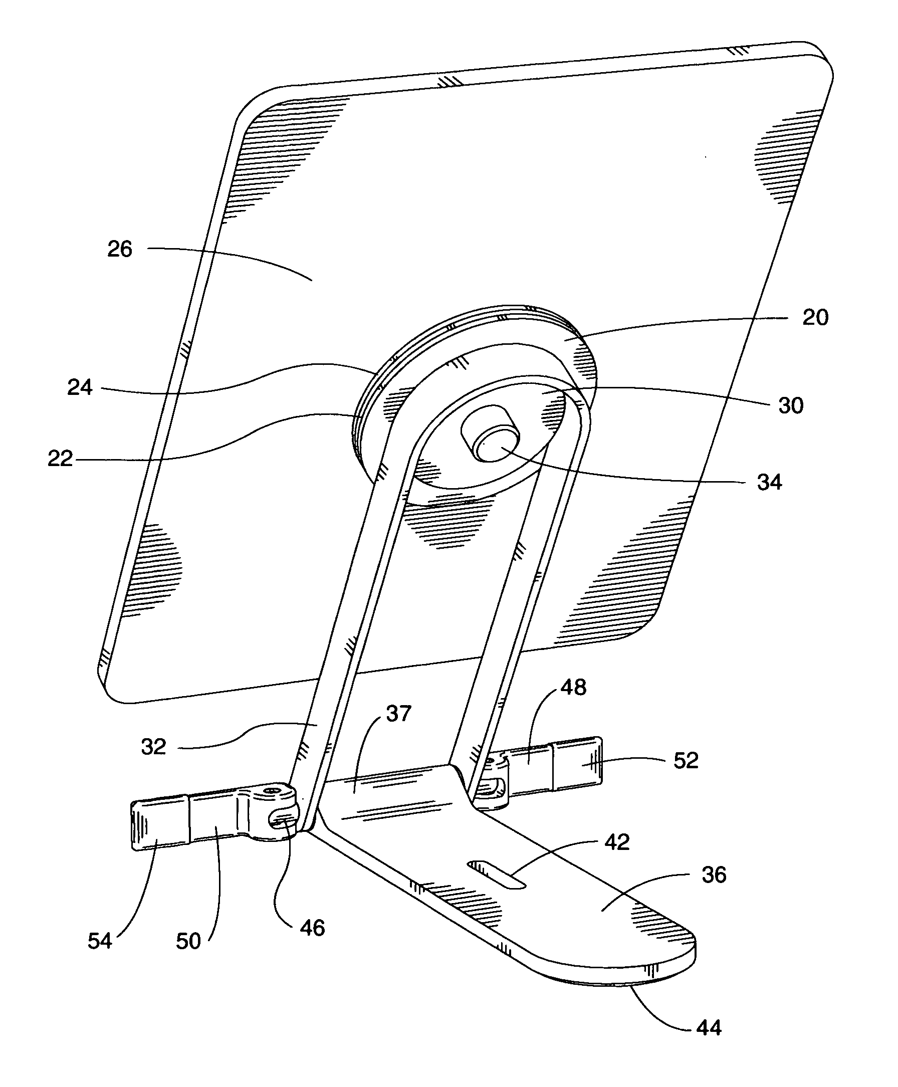
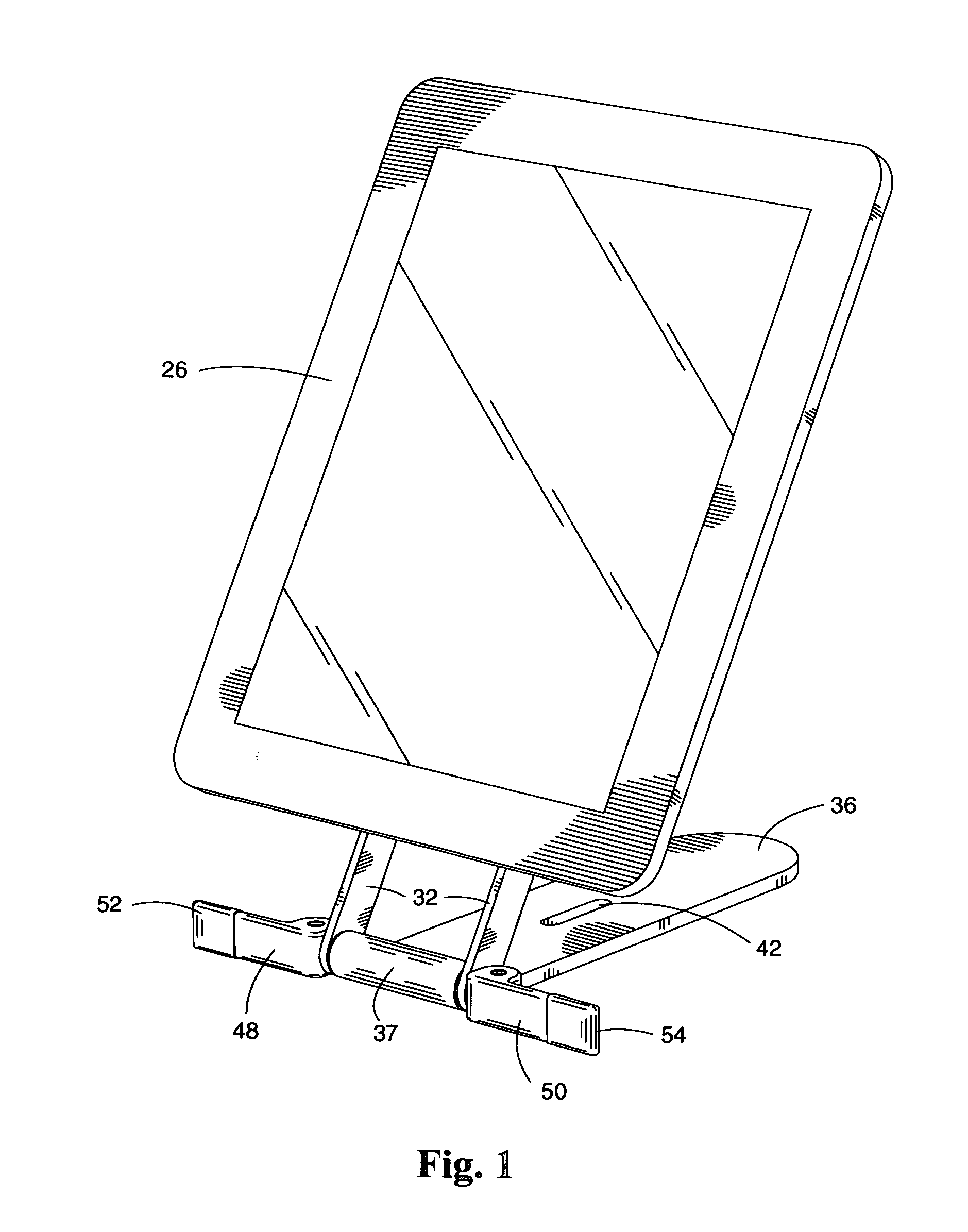
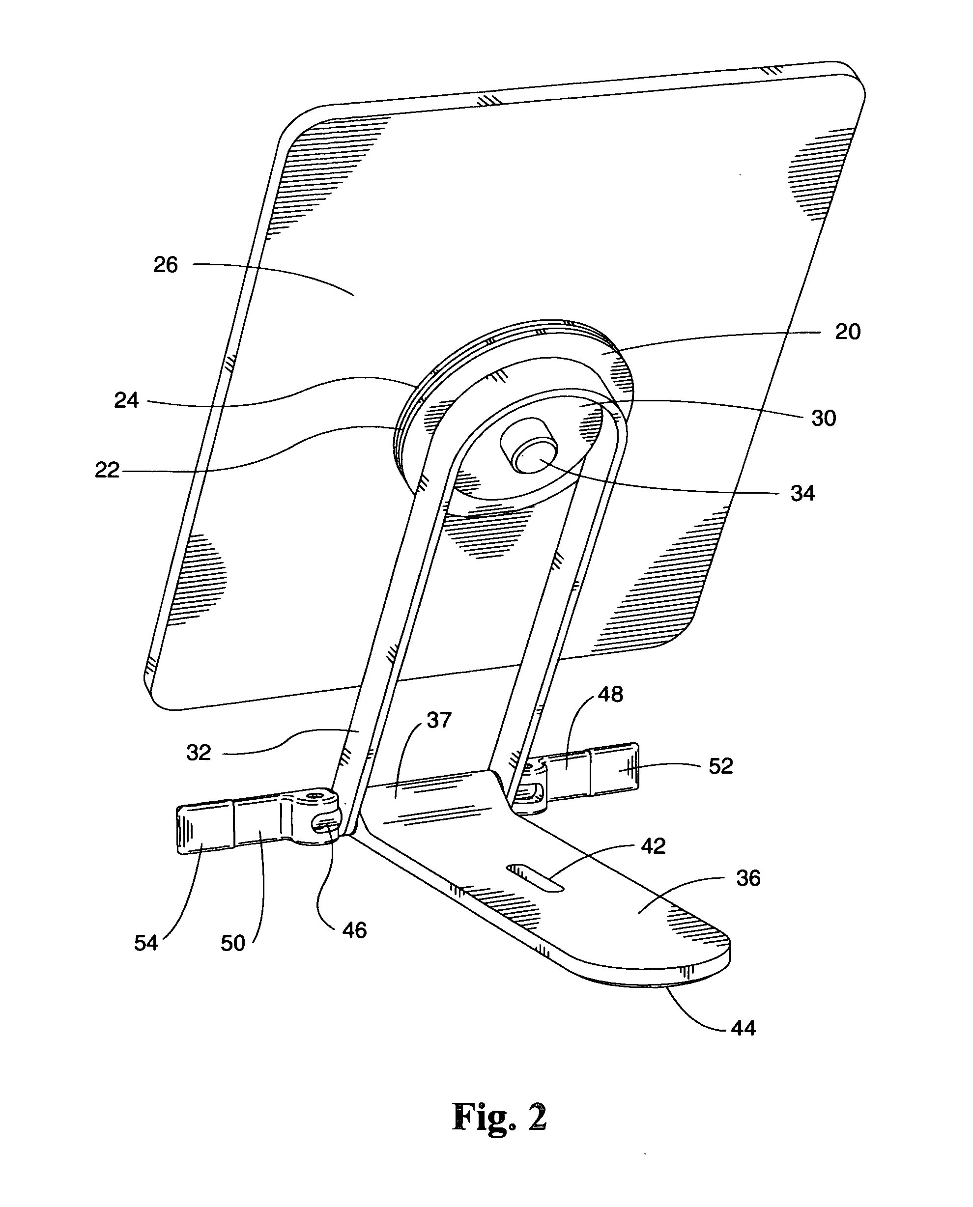
[0031]Referring to the drawings and initially to perspective FIGS. 1, 2, and 15, and to exploded FIGS. 16-18, a multi-positional stand and under cabinet mount for a tablet computer (of prior art) in accordance with the preferred embodiment of the present invention comprising a base member 36, a hinge member 32, a mounting plate 20, 2 cam-actuated handles 48 and 50, a hinge pin 46, 2 partially-threaded locking pins 56 and 58, and a base mount 60. Base member 36 can be solid and substantially flat and approximately 4 times as deep as it is wide. The sides of base member 36 are parallel near the front. The front area of base member 36 has a raised front area 37 that is cylindrical in shape and is oriented with its center axis going side to side. The raised front area 37 can flow smoothly into the flat shape of base member 36 and is oriented so that the bottom most point of thick area 37 and the bottom of base member 36 are on the same plane. Raised front area 37 of base member 36 has a...


PUM


Abstract

A multi-positional stand and under-cabinet mount for a tablet computer comprising a mounting plate, a hinge member, a base member, a hinge pin, 2 cam-actuated handles, a base mount and an attachment knob. The mounting plate can be temporarily coupled to the center of the back of a tablet computer with hook-and-loop (or similar) two-part, fastening material (of prior art). The mounting plate can be rotationally attached to the flat face on the top front of the hinge member allowing the attached tablet computer to rotate. The bottom of the hinge member can be pivotally attached to the front of the base member with the hinge pin oriented horizontally allowing the recline angle of said tablet computer to be adjusted. The angular position of the hinge member and base member can be locked in place, in any one of an infinite number of angular positions within a range, by the manipulation of the 2 cam-actuated handles. The hinge member can fold down on top of the base member and the cam actuated handles can fold towards the base member for a compact, portable configuration. The base mount can attach to the bottom of a cabinet or shelf with screws. The stand can be temporarily mounted to the base mount (in an upside-down position) with an attachment knob and can be manipulated, touch, rotated, tilted left or right, or forward and back, or fully retracted underneath the cabinet or shelf.

Description

FIELD OF INVENTION[0001]This invention relates to a multi-positional, portable tabletop stand and under cabinet / shelf mount for a tablet computer.DESCRIPTION OF PRIOR ART[0002]Since tablet computers are a new invention there is not much prior art for tablet computer stands. Most of the prior art pertains to mounting systems for computer monitors, television screens, cell phones, DVD players and GPS units. U.S. Pat. No. 6,340,146, by Tzeng, is a swing down mounting system for an LCD screen in which the screen can lock in one of a series of angular positions. U.S. Pat. No. 7,028,961, by Dittmer et al., is a mounting system for a flat screen which is designed to attach to a wall and allows the screen to be pivoted both horizontally and vertically within a range, however, it is not designed to be portable or sit on a horizontal surface. U.S. Pat. No. 6,962,314, by Hsu, is a multifunctional holder designed to clamp securely to surface, but does not specify screen rotation. U.S. Pat. No. ...

Claims


Application Information

Patent Timeline
Patent Type & Authority Applications(United States)
IPC IPC(8): H05K7/14
CPCF16M11/105F16M11/2021F16M2200/022F16M13/02F16M13/00
Inventor WETZEL, SHELLEY ANNEPALMQUIST, MARK STEVEN
Owner AUTUMN HORIZONS
Why Eureka
Try Eureka