
Hand-held wand mixer

Inactive Publication Date: 2005-12-13
LIN KING YUAN
View PDF35 Cites 51 Cited by
  • Summary
  • Abstract
  • Description
  • Claims
  • Application Information

AI Technical Summary

Benefits of technology

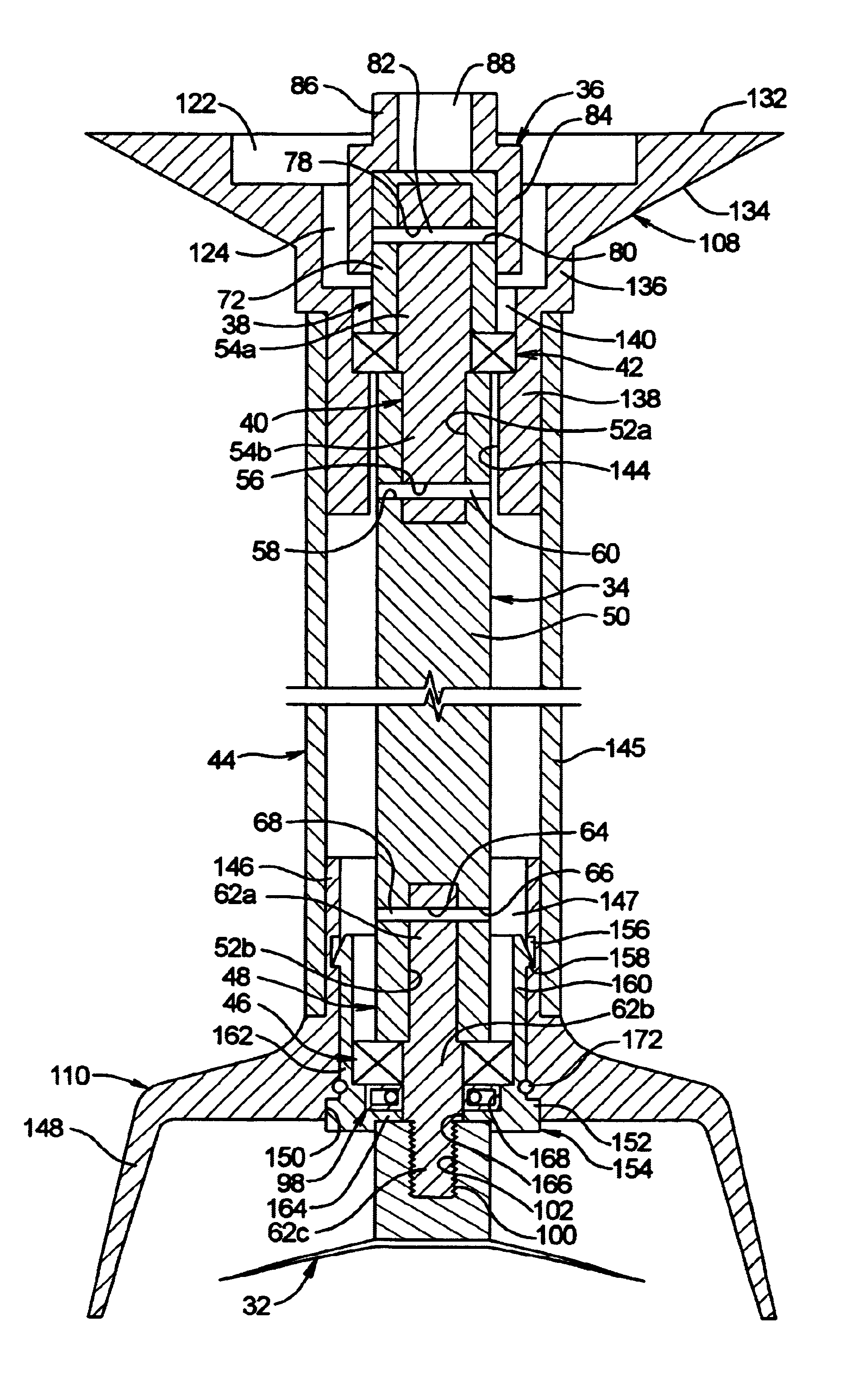
[0015]The drive connections between the motor shaft and drive shaft may comprise an eternally-splined male member and an internally-splined female member that receives the externally splined member axially therein. The drive shaft may comprise an elongate primary shaft having a relatively large diameter for efficient transmission of torque, and first and second stub shafts mounted coaxially at the ends thereof, the stub shafts having relatively smaller diameters for engaging inner races of the upper and lower bearings. The lower stub shaft may have a threaded lower end for threaded attachment of the mixing tools thereto, allowing a variety of processing tools to be easily exchanged or removed for cleaning. The upper stub shaft, in turn, may have an upper end having one of the drive connections mounted thereto.
[0016]The drive shaft has a substantial length in order that the processing tool can fully access deep bowls and other vessels. As noted above, this extended length has the potential for generating significant bending loads on the motor bearings if not otherwise reacted, particularly when processing viscous substances. Unlike prior mixers which rely on the motor bearing to support the upper end of the drive shaft, the tubular shaft housing and upper and lower bearings in the present invention provide lateral support for both ends of the drive shaft. The motor bearing loads are therefore reduced, providing increased motor longevity and reduced maintenance. As discussed below, the drive shaft is also held against bending or pivoting when the wand assembly is removed for cleaning, thus preserving the integrity of the seal member at the lower end of the assembly.
[0017]The upper end of the shaft housing is secured to the motor housing by a detachable coupling, which may comprise a bayonet-type coupling. The female portion of the bayonet coupling may comprise a hollow coupling member that is mounted at the upper end of the shaft housing and has an enlarged upper end that forms an enlarged mating surface for the coupling, with slots and grooves that form the female portion of the coupling being recessed into the mating surface. The male portion of the bayonet coupling may comprise a corresponding mating surface and male lugs mounted on the lower end of the motor housing. The large contact area between the mating surfaces on the motor and shaft assemblies at the bayonet joint effectively reacts any bending loads, providing a secure, stable connection that reducing stresses in the motor housing.
[0018]In combination with the detachable, slide-apart coupling between the drive shaft and motor shaft, the bayonet-type coupling forms a quick-detach connection that allows the wand assembly to be removed from the motor assembly as a single unit and without use of any tools. This greatly facilitates the cleaning process, since the exterior components that are likely to be covered with debris can be cleaned without additional disassembly: As noted above, the seal member encloses the lower end of the tubular housing and prevents debris and fluids from entering, so that full disassembly is not normally required in order to achieve proper cleaning and sanitation.
[0020]The plug insert may further comprise a plurality of resilient tab portions that extend upwardly from the cylindrical wall so as to detachably secure the plug insert in the lower end of the tubular housing. Each of the tab portions may comprise a tapered lip on an outer surface thereof for detachably engaging a cooperating groove formed an inner surface of the tubular housing. The resiliency of the tabs allows the tabs to deflect inwardly as the cup-shaped pug is inserted, and then expand outwardly to engage the locking groove when the plug is fully inserted.

Problems solved by technology

The mixing process is inherently messy, and the processing tool, blade guard and tubular housing invariably become covered with particulate food or other residue.
In addition, the rapidly rotating tool or blade often acts somewhat like a pump, generating upward flow that tends to force residue into the tubular housing where the drive shaft emerges.
Because the drive shaft bearing and other moving parts reside within the housing, any influx of contaminate material may degrade the integrity of these components.
Furthermore, any food residue that evades the cleansing process can quickly become a source of bacterial contamination, posing potentially serious health consequences.
While such approaches may help ensure that the mixer is safely sanitized, the disassembly and re-assembly that is required is both tedious and time consuming.
In addition, such assemblies tend to be complex and expensive to produce.
While some of these designs may reduce the amount of seepage entering the tubular wand during operation of the mixer, their general design is such that the sealing mechanism is rendered ineffective during actual cleaning of the assembly.
For instance, due to the weight and bulk of the motor assembly, plus the fact that most motor housings are not intended to be fully immersible, it is generally required that the drive shaft and its tubular housing be removed from the motor for cleaning.
Thus, when the drive shaft and its housing are detached from the motor assembly, the free end of the drive shaft (which was previously coupled to the motor shaft) is released from its fixed spatial relationship with the tubular housing and tends to bend or pivot within the housing as the assembly is cleaned, inevitably causing deformation of the seal at the opposite end.
Water and debris then enter the tubular housing through the deformed seal and contaminate the internal components.
Yet another deficiency of this configuration is that the lateral loads imparted to the upper end of the drive shaft during operation of the mixer must be reacted by the motor bearing alone.
The added loading results in increased motor wear, thus reducing motor longevity and increasing maintenance requirements.

Method used


Image

  • Hand-held wand mixer
  • Hand-held wand mixer
  • Hand-held wand mixer

Examples


Embodiment Construction

a. Motor and Motor Housing

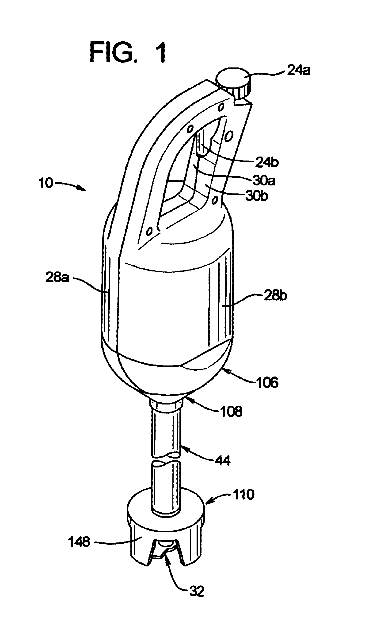
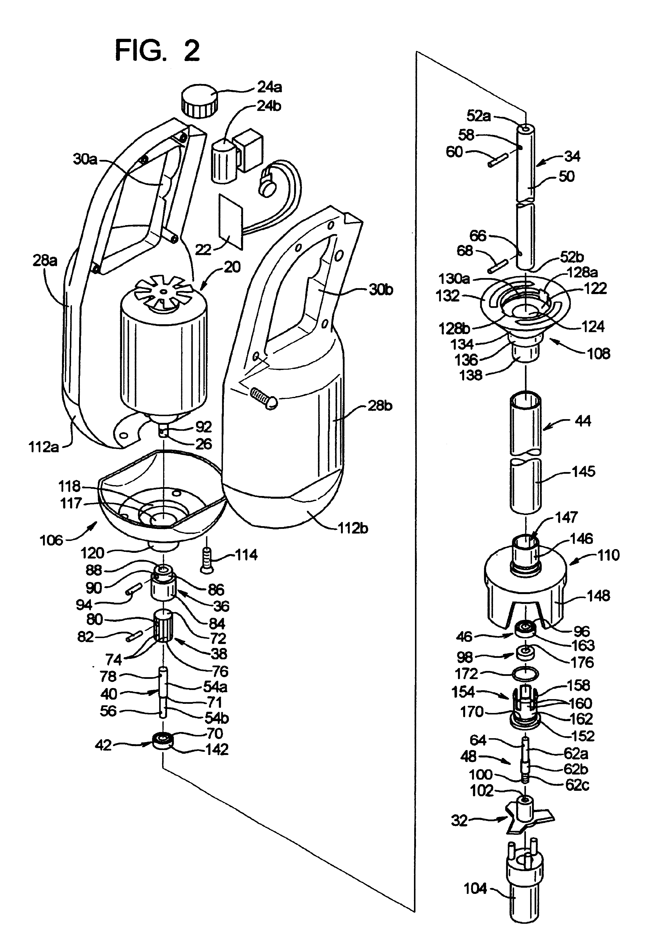
[0030]FIG. 1 provides an isometric overview of a hand-held wand mixer 10 in accordance with the present invention, while FIG. 2 provides an exploded isometric view of the mixer. As shown in these figures, the mixer is powered by a generally conventional, variable speed electric motor 20, of a type typically used for such applications, and includes appropriate control circuitry 22 and manually operable switches and controls 24a,b. Output from the motor is delivered by a motor shaft 26, which typically rotates at speeds of approximately 3000 to 10,000 rpm. To provide splash protection and guard the user against shock and moving parts, the motor 20 is enclosed within a protective motor housing 28a,b having an integrated handle 30a,b that provides a handgrip for manipulating the mixer. The motor housing 28a,b, may be constructed of any suitable strong, lightweight material, such as plastic or aluminum, but is preferably molded from impact-resistant plastic due ...


PUM


Abstract

A wand mixer having a wand assembly that is detachable from the motor assembly as a single unit. The wand assembly includes a drive shaft that is enclosed within a tubular housing having a seal at the lower end for preventing entry of fluids and debris. First and second bearings at the ends of the tubular housing support both ends of the shaft so as to prevent deformation and damage of the seal when the wand assembly is removed from the motor assembly for cleaning. The wand assembly mounts to the motor assembly using a bayonet-type connection, and the motor and drive shafts are interconnected by an externally splined member that is received axially in an internally splined sleeve. The wand assembly can therefore be removed or mounted to the motor assembly by a convenient, manual turning and axial movement of the components.

Description

BACKGROUND OF THE INVENTION[0001]a. Field of the Invention[0002]The present invention relates generally to portable electrical mixers, and, more particularly, to a hand-held wand mixer for mixing, chopping, blending, and general processing of food items and similar materials.[0003]b. Background Art[0004]In the commercial food service industry, as well as certain other fields such as the chemical and pharmaceutical industries, it is common to utilize comparatively large, hand-held electric mixers for the bulk preparation of food items and other products. Examples of such food items include various batters, soups, salads, and so on. Such mixers are generally used in combination with a large bowl or other mixing vessel in which the food items or other materials are combined. A variety of attachments and tools are employed, such as chopper blades, whisks, kneading tools or comminuting rods, to mix, blend, whip, chop or emulsify the food or other material to the desired consistency.[0005...

Claims


Application Information

Patent Timeline
IPC IPC(8): A47J43/044A47J43/07
CPCA47J43/0705A47J2043/04427
Inventor LIN, KING-YUAN
Owner LIN KING YUAN
Learn More