
Developer amount detector, and developer container, development device, and image forming apparatus incorporating same

Active Publication Date: 2012-07-26
RICOH KK
View PDF2 Cites 30 Cited by
  • Summary
  • Abstract
  • Description
  • Claims
  • Application Information

AI Technical Summary

Benefits of technology

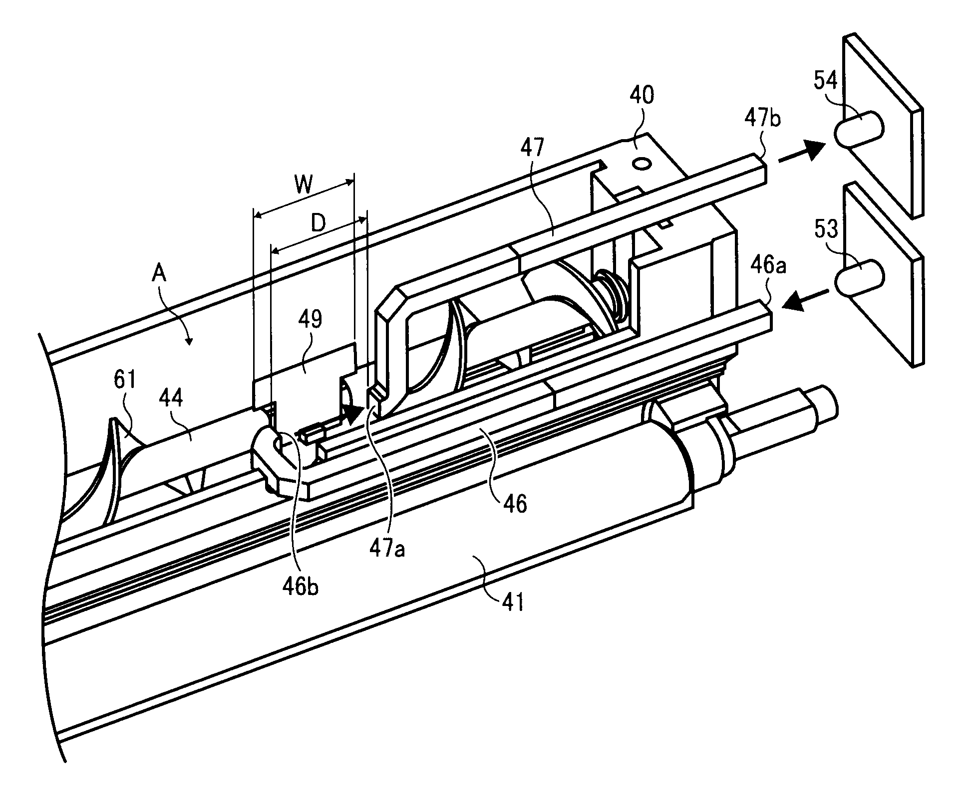
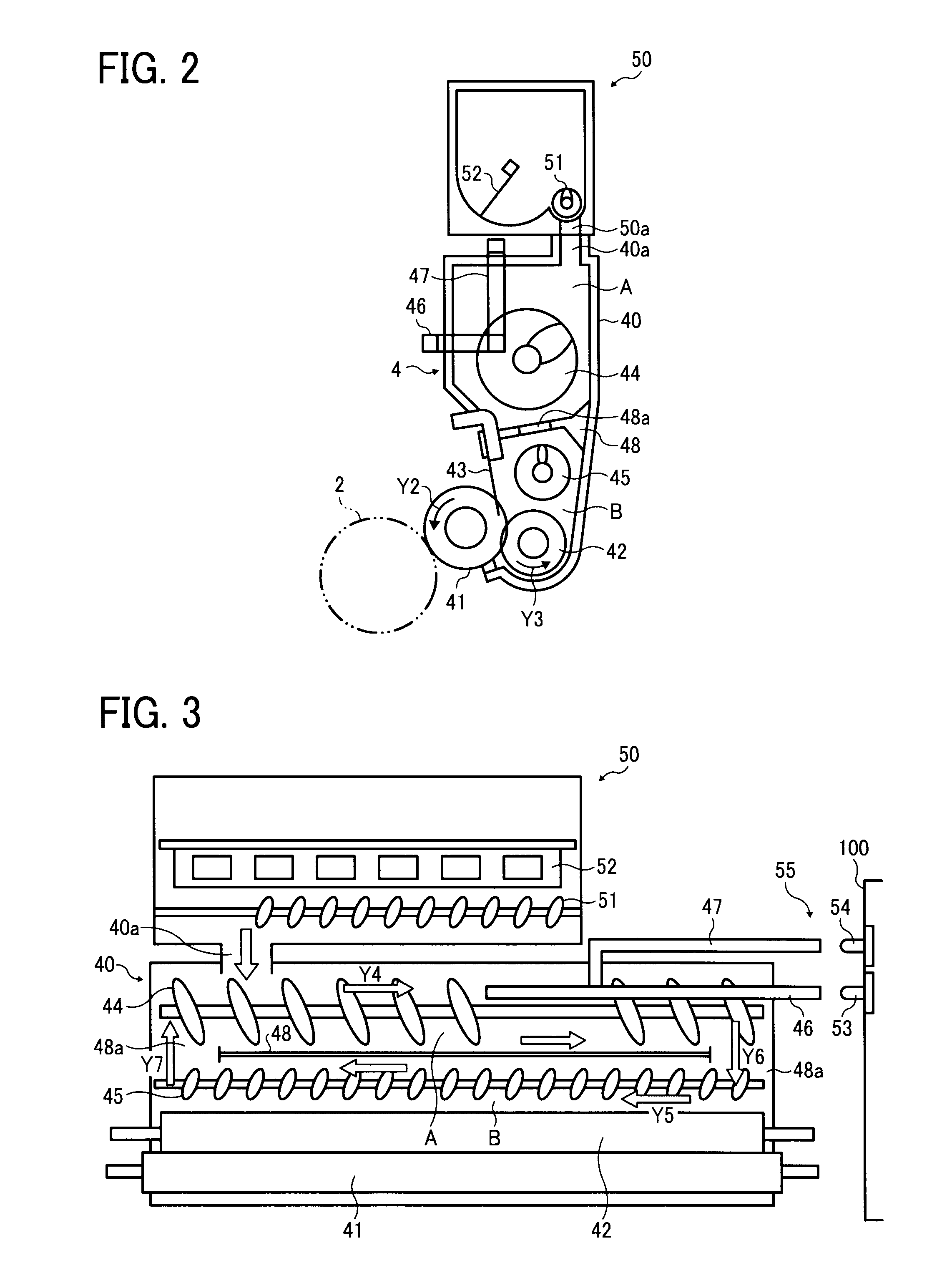
[0095]As described above, even if the surface of the developer fluctuates and inclination thereof becomes unstable as the developer is transported, adverse effects caused by the fluctuations to the light transmission can be reduced. Additionally, the arrangement in which the light transmission path L is disposed within the locus of rotation of the developer conveyance member, where the toner conveyance and loosening effects are sufficient, can prevent the developer from blocking the light transmission path L when the amount of developer is less than the reference amount. Consequently, detection error and tolerance in detection can be reduced, securing a high degree of accuracy in the developer amount detection. Therefore, insufficient image density due to shortage of toner can be prevented or reduced. Additionally, replacement of toner cartridges in which a sufficient amount of toner still remain can be prevented.
[0095]As described above, even if the surface of the developer fluctuates and inclination thereof becomes unstable as the developer is transported, adverse effects caused by the fluctuations to the light transmission can be reduced. Additionally, the arrangement in which the light transmission path L is disposed within the locus of rotation of the developer conveyance member, where the toner conveyance and loosening effects are sufficient, can prevent the developer from blocking the light transmission path L when the amount of developer is less than the reference amount. Consequently, detection error and tolerance in detection can be reduced, securing a high degree of accuracy in the developer amount detection. Therefore, insufficient image density due to shortage of toner can be prevented or reduced. Additionally, replacement of toner cartridges in which a sufficient amount of toner still remain can be prevented.

Problems solved by technology

Detection accuracy of light transmission-type developer amount detectors, however, can be degraded in configurations in which developer is thus transported.
If the slant surface J of the toner T positioned in a light transmission path L between the first light guide 400 and the second light guide 500 fluctuates as shown in FIG. 9 as the screw 300 rotates, the degree of light transmission varies, resulting in detection error.
In other words, in the configuration in which the light transmission path L between the first light guide 400 and the second light guide 500 is perpendicular to the axis of the screw 300 as shown in FIG. 9, the degree of light transmission is susceptible to fluctuations in the surface of the toner T. Thus, it is difficult to attain a high degree of accuracy in detection of the toner amount.

Method used


Image

  • Developer amount detector, and developer container, development device, and image forming apparatus incorporating same
  • Developer amount detector, and developer container, development device, and image forming apparatus incorporating same
  • Developer amount detector, and developer container, development device, and image forming apparatus incorporating same

Examples


Embodiment Construction

[0026]In describing preferred embodiments illustrated in the drawings, specific terminology is employed for the sake of clarity. However, the disclosure of this patent specification is not intended to be limited to the specific terminology so selected, and it is to be understood that each specific element includes all technical equivalents that operate in a similar manner and achieve a similar result.

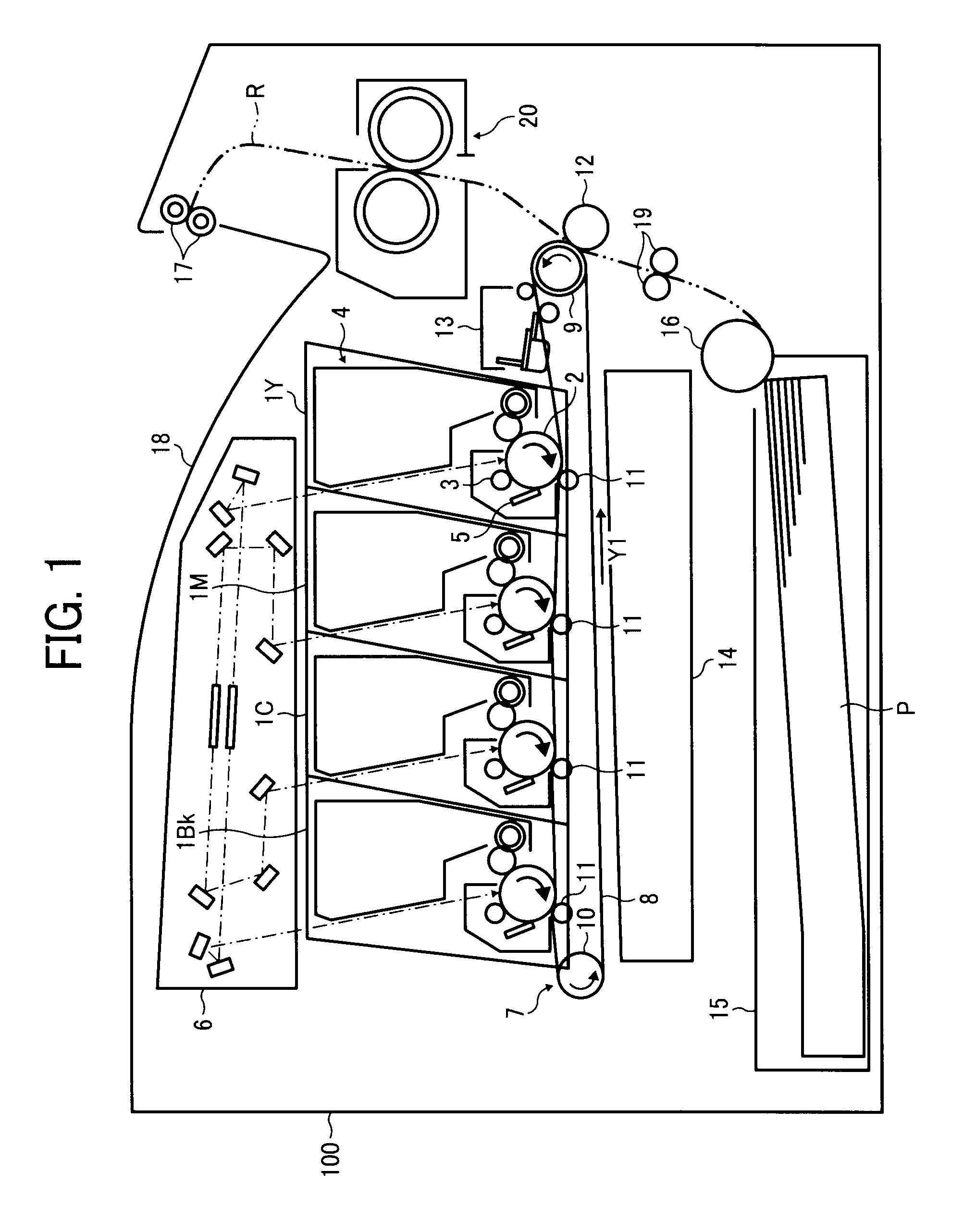
[0027]Referring now to the drawings, wherein like reference numerals designate identical or corresponding parts throughout the several views thereof, and particularly to FIG. 1, a multicolor image forming apparatus according to an embodiment of the present invention is described.

[0028]It is to be noted that the suffixes Y, M, C, and K attached to each reference numeral indicate only that components indicated thereby are used for forming yellow, magenta, cyan, and black images, respectively, and hereinafter may be omitted when color discrimination is not necessary.

[0029]Referring to FIG....


PUM


Abstract

A development device includes a development housing, a first developer conveyance member, a developer bearer, and a developer amount detector to detect an amount of developer in the development housing. The developer amount detector includes a light-emitting element, a right-receiving element, a first light guide including a first end from which light enters and a second end disposed inside the development housing, and a second light guide including a first end positioned inside the development housing across a predetermined distance from the second end of the first light guide and a second end from which the light exits. The second end of the first light guide and the first end of the second light guide are arranged in an axial direction of the first developer conveyance member with a light transmission path therebetween partly inside a locus of rotation of the first developer conveyance member.

Description

CROSS-REFERENCE TO RELATED APPLICATIONS[0001]This patent application is based on and claims priority pursuant to 35 U.S.C. §119 to Japanese Patent Application No. 2011-014215, filed on Jan.26, 2011, in the Japan Patent Office, the entire disclosure of which is hereby incorporated by reference herein.FIELD OF THE INVENTION[0002]The present invention generally relates to a developer amount detector, and a development device, a process unit, and an image forming apparatus including a developer amount detector.BACKGROUND OF THE INVENTION[0003]There are image forming apparatuses, such as copiers, printers, facsimile machines, or multifunction machines including at least two of these functions, that include process units in which a development device, a toner cartridge, and photoreceptor are housed in a common unit casing as a modular unit removably installable in a main body of the image forming apparatus. Developer contained in process units is consumed in image development, and accordi...

Claims


Application Information

Patent Timeline
IPC IPC(8): G03G15/08
CPCG03G15/0831G03G2215/0827G03G15/0893G03G15/0856G03G15/0862G03G2215/0891
Inventor KUBOTA, TOMOHIRONAKATAKE, NAOKIOOYOSHI, HIROBUMIYOSHIDA, TOMOFUMISHIMIZU, YOSHIYUKIHAMADA, MANABUTSURITANI, SHOH
Owner RICOH KK
Learn More