
Device and method for locating a pulp chamber in a tooth

a technology a tooth is applied in the field of dental devices and methods for locating a pulp chamber in a tooth, which can solve the problems of severe toothache and/or infection, difficult to ascertain the location of the pulp chamber, and inability to move the infection into the bone, etc., and achieves the effect of convenient attachment to the tooth

Inactive Publication Date: 2012-07-26
KRASNER PAUL R
View PDF11 Cites 2 Cited by
  • Summary
  • Abstract
  • Description
  • Claims
  • Application Information

AI Technical Summary

Benefits of technology

The device enables reliable and precise access to the pulp chamber, reducing the risk of tooth damage and ensuring successful root canal procedures by providing accurate directional guidance, overcoming limitations of existing methods like X-rays and anatomical knowledge.

Problems solved by technology

When the pulp becomes damaged, either due to tooth decay, or to dental restoration procedures or trauma, the pulp can become severely inflamed and then infected.
This degeneration will often result in a severe toothache and / or a movement of the infection into the bone near the tooth roots.
Therefore, when the pulp becomes damaged, it must be removed.
But in a real clinical setting, the location of the pulp chamber is often very difficult to ascertain.
1) The crown of the tooth may be very heavily restored with old amalgams, composite fillings, or gold inlays.
2) The tooth may have an artificial crown that hides the underlying normal tooth structure. Thus, the normal anatomy of an unrestored tooth, or a lightly restored tooth, which is usually used as guidance for initial penetration, is gone. The artificial crown may be incorrect anatomically, and may give no indication of the true occlusal anatomy of the tooth which is normally used as a guide for initial penetration.
3) The tooth may be tilted or rotated in any direction. When this happens, a crown may be constructed in such a position to correct the tilting discrepancy. This tilting is likely to confuse the dentist with regard to the proper penetration angle for a dental burr.
4) In an elderly patient, the walls of the pulp chamber and root canals narrow, and the pulp chamber may not be easily seen or observed.
5) Almost all dentists currently perform root canal treatments with the patient lying back in a prone position. When the patient is lying back, the angle of the tooth is further distorted, and the correct penetration point and angle of penetration becomes difficult to ascertain.
6) In practice, in many teeth, the pulp chamber may be very small, thready, and calcified, and very different from the idealized concept illustrated in the drawings. The dentist must often penetrate into areas that could be as small as 1 mm in diameter. The margin for error is therefore very, very small.
All of the above conditions, as well other clinical factors, such as inexperience, may lead to difficulty in finding the pulp chamber.
An error in locating the pulp chamber can have severe consequences.
First, failure to locate the pulp chamber may prevent the pulp from being removed, and therefore the patient's pain cannot be relieved, and the procedure cannot be performed.
Secondly, if the exact position of the pulp chamber is not known, the penetrating burr may deviate from the proper path needed to enter the pulp chamber.
This deviation can cause perforation of the crown, which can lead to loss of the tooth.
Finally, excessive digging around the inside of the tooth can weaken the tooth.
The above methods are ineffectual.
Knowledge of tooth anatomy is often unhelpful because the structure of the tooth may have dramatically changed due to previous dental work.
And clinical observations can be deceptive due to the presence of an artificial crown or other restoration.
However, the cited article does not provide a practical solution to the problem of locating the pulp chamber.
This process is very difficult because the gingiva at the neck of the tooth is often swollen and inflamed.
Moreover, the process of mentally imaging the structure of the tooth is difficult for many dentists.
In summary, dentists currently have surprisingly little practical information about the true relationship between the observed crown of the tooth, and the root upon which it sits.

Method used


Image

  • Device and method for locating a pulp chamber in a tooth
  • Device and method for locating a pulp chamber in a tooth
  • Device and method for locating a pulp chamber in a tooth

Examples


Embodiment Construction

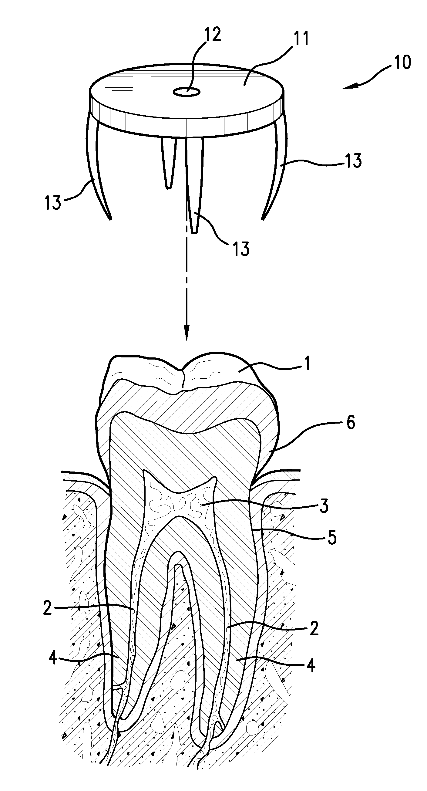
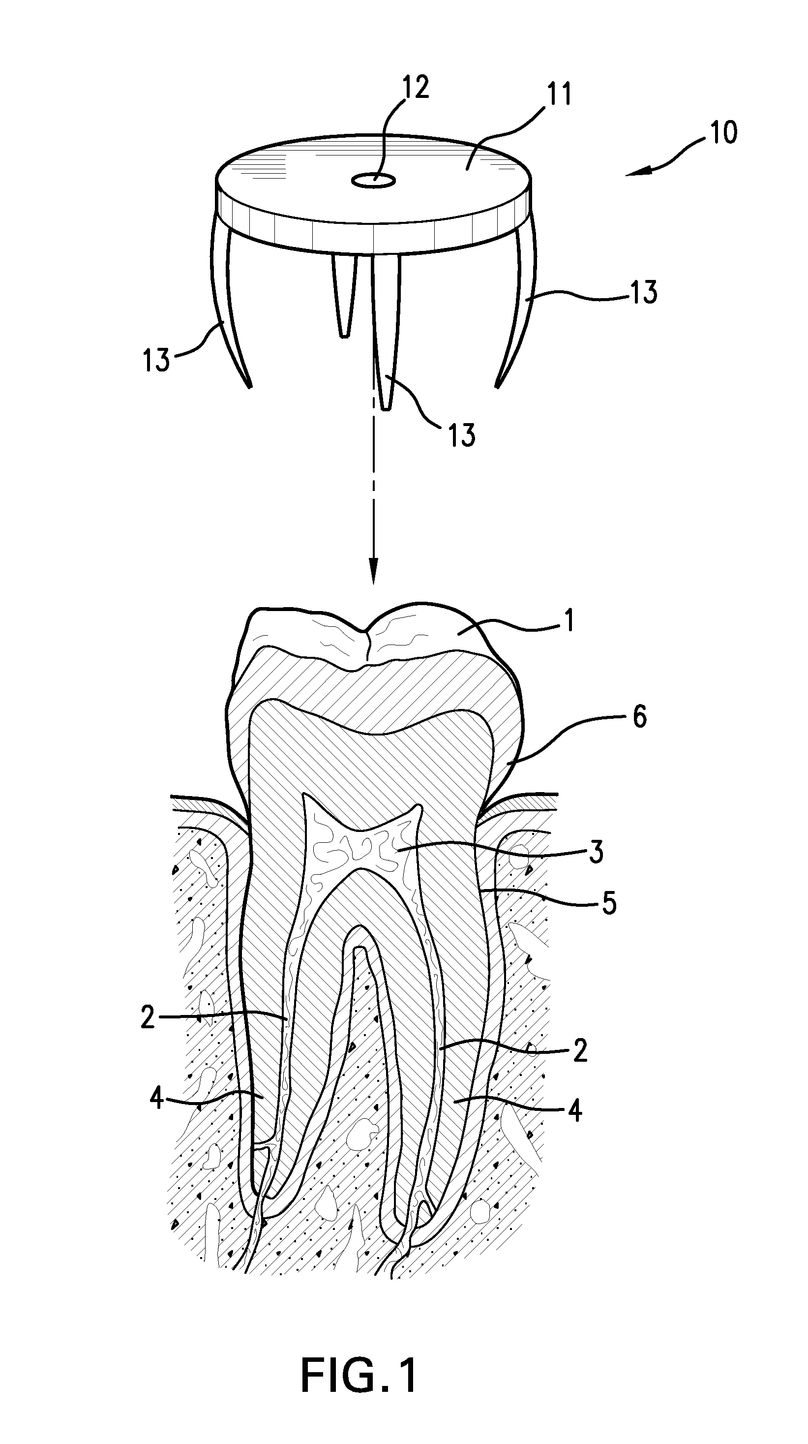
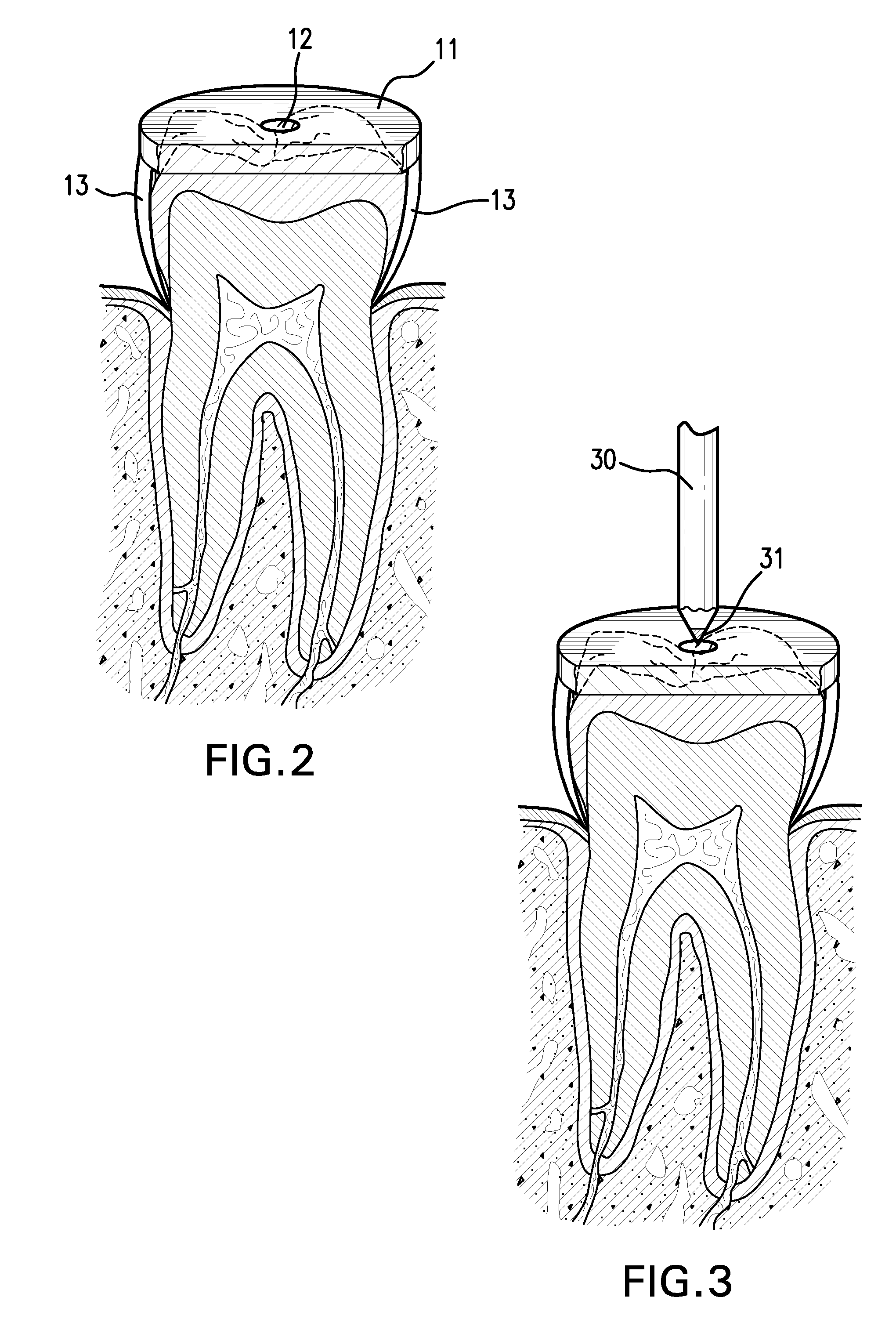
[0046]The device of the present invention enables a dentist easily to locate the pulp chamber of a tooth. Thus, in this specification, the device will be called a pulp chamber locator.

[0047]FIG. 1 shows the pulp chamber locator 10 before it has been attached to the crown 1 of a tooth. The pulp chamber locator comprises a plate 11 which is generally flat and of generally circular shape. In the center of the plate is a hole 12. A plurality of struts 13 are connected to the plate, at the periphery of the plate, and extend downward from the plate. Each strut thus has a first end which is attached to the plate, and a second end which is a free end. In the embodiment shown, there are four struts. In most preferred embodiments, there may be four to six such struts, but the number can be varied.

[0048]Preferably, the plate and the struts are made of plastic, but the invention is not limited to a particular choice of material. Preferably the plate and the struts are formed of one piece. The s...


PUM


Abstract

A pulp chamber locator assists a dentist in performing a root canal procedure. The device includes a generally circular plate and a plurality of struts extending from the plate. The plate has a hole in the vicinity of its center. The device is inserted over a tooth, such that the struts engage the cemento-enamel junction of the tooth. The hole then indicates the proper point of entry for a dental instrument. The device may also include a rotatable indicator for showing the proper angle of entry, to insure that the instrument reaches the pulp chamber of the tooth. The dentist adjusts the position of the indicator, based on information provided by an X-ray or equivalent, and positions the dental instrument so as to be generally parallel with the indicator.

Description

CROSS-REFERENCE TO PRIOR APPLICATION[0001]This is a continuation of U.S. patent application Ser. No. 12 / 476,598, filed Jun. 2, 2009.BACKGROUND OF THE INVENTION[0002]The present invention relates to the field of dentistry, and provides a device and method useful in performing a root canal procedure. Specifically, the invention enables a dentist to find the proper entry point, and entry angle, to access the pulp chamber of a tooth.[0003]Root canal treatment is performed in response to an infection of the pulp of the tooth. The pulp is found in an internal chamber, which is beneath the crown and not visible from the outside. When the pulp becomes damaged, either due to tooth decay, or to dental restoration procedures or trauma, the pulp can become severely inflamed and then infected. This degeneration will often result in a severe toothache and / or a movement of the infection into the bone near the tooth roots. Therefore, when the pulp becomes damaged, it must be removed. This is done t...

Claims


Application Information

Patent Timeline
Patent Type & Authority Applications(United States)
IPC IPC(8): A61C19/04
CPCA61C5/02A61C1/082A61C5/40
Inventor KRASNER, PAUL R.
Owner KRASNER PAUL R
Learn More