Plunger lift control system arrangement

Active Publication Date: 2012-08-02
WELL MASTER CORP
View PDF1 Cites 36 Cited by
  • Summary
  • Abstract
  • Description
  • Claims
  • Application Information

AI Technical Summary

Benefits of technology

[0031]The invention thus also comprises a method of increasing the output efficiency of an oil or gas well by minimizing the time required to recycle a plunger travelling between an upper end of a multi-sectioned metal walled tubing string and a bottom end of the metal walled tubing string of that well, comprising the steps of: sending a plunger down the walled tubing string within a well casing to a bottom portion of the tubing; generating a signal upon the plunger's reaching the bottom of the tubing; transmitting the signal generated by the plunger at the bottom of

Problems solved by technology

The presence of liquid within that well, its production strain or tubing or casing, may be detrimental to the productive capacity of the well, as it exerts a back pressure on the formation limiting the flow into the well bore.
As the flow velocity continues to slow, the gas phase can no longer support liquid in either slug form or droplet form.
This procedure however may lose valuable production time going unused as wel

Method used


Image

  • Plunger lift control system arrangement
  • Plunger lift control system arrangement
  • Plunger lift control system arrangement

Examples


Example

DETAILED DESCRIPTION OF THE DRAWINGS

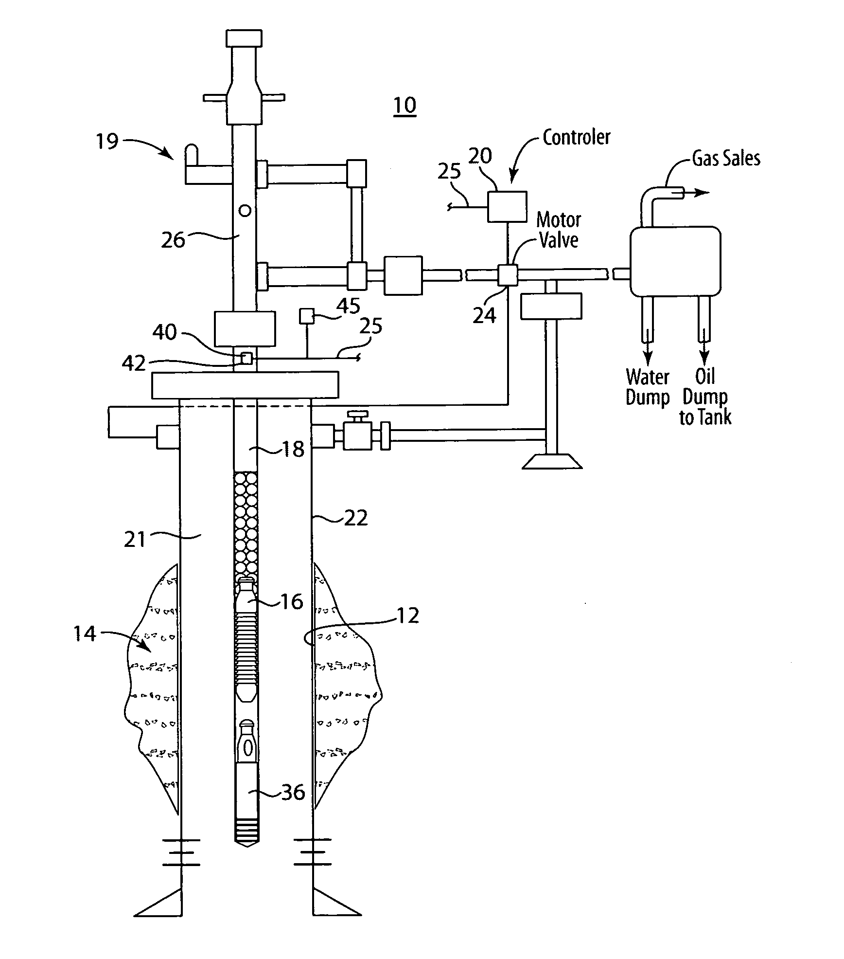
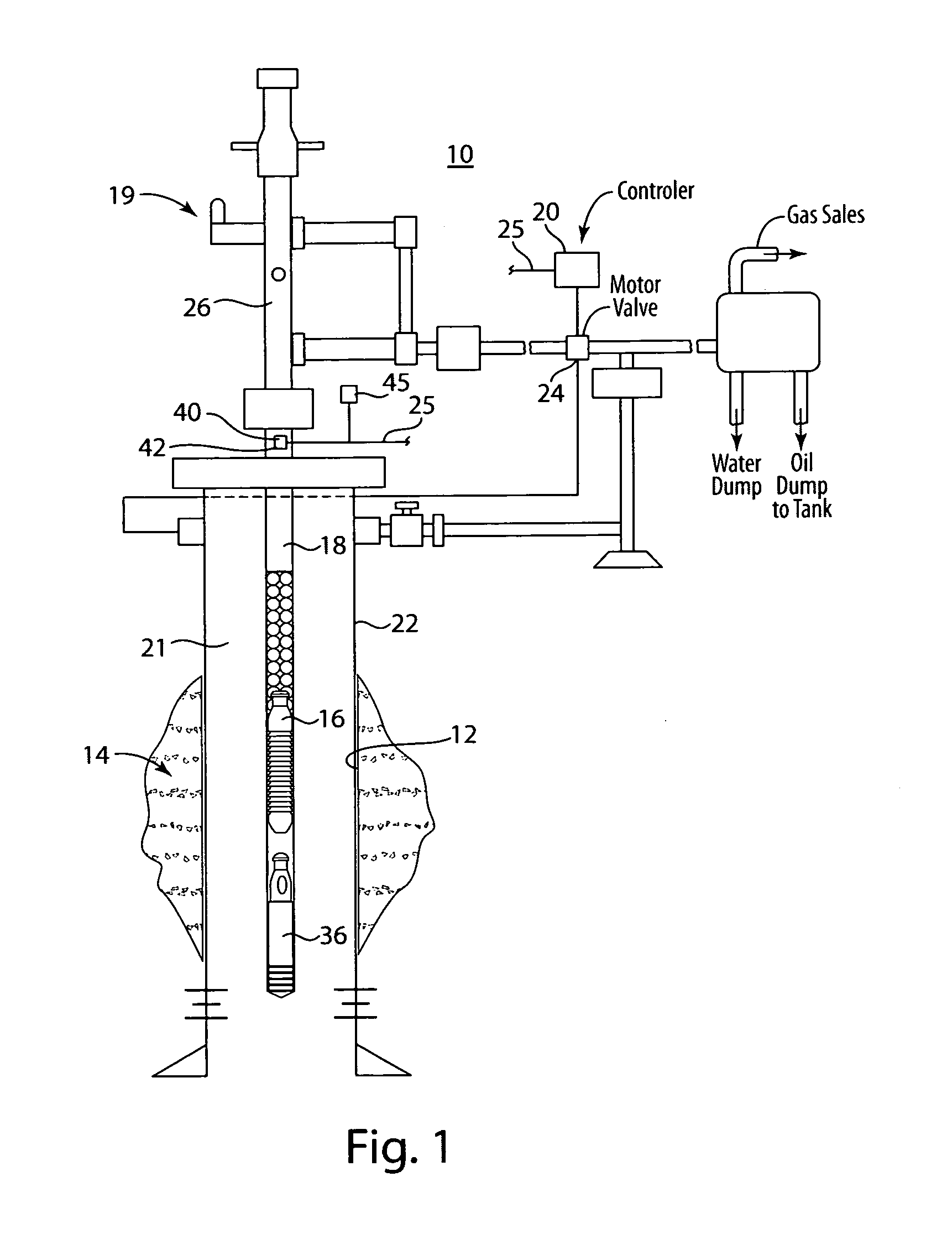
[0036]Referring now to the drawings in detail, and particularly to FIG. 1, there is shown a side view of an installed plunger lift control system 10 set up in a borehole 12 of a well 14. The plunger lift control system 10 includes a plunger arrangement 16. The plunger 16 in a plunger lift system in an oil and gas well is vertically movable in the production tubing string 18 of the well 14, and falls to the bottom of that production tubing string 18 and thence sends a signal “S” to a controller 20 with the wellhead 19 at the top of the well 14 that the plunger 16 has arrived at the bottom of the tubing string 18, identified by an arrangement described hereinbelow. The production tubing string 18 is arranged within an outer casing 22 which casing 22 extends and defines the depth of the well 14, there being an elongated annulus 21 between the tubing string 18 and the casing 22. The tubing string 18 does not extend the full length of the casing 22. Th...


PUM


Abstract

A plunger lift control system for improving the output efficiency of an oil or gas well by a real-time reporting arrangement, the system comprising: a tubing string having an upper end and a lower end, the tubing string arranged within a well casing for receiving a plunger traveling therethrough, a plunger having a sound generating function therewith, so as to transmit a real-time lower-end location signal from the plunger to a signal sensor and processor arranged in communication with a system controller arranged at the upper end of the tubing.

Description

BACKGROUND OF THE INVENTIONField of the Invention[0001]This invention relates to the operation of oil and gas wells, and more particularly to systems for increasing the production of resources from those wells, and claims the benefit of provisional application 61 / 461,402, filed 14 Jan. 2011, this application also being a C-I-P of application Ser. No. 12 / 807,808 filed on Sep. 14, 2010 which is a C-I-P of 12 / 217,756, filed on Jul. 8, 2008, now U.S. Pat. No. 7,793,728 is a division of Ser. No. 11 / 350,367 filed Feb. 8, 2006 which is now U.S. Pat. No. 7,395,865 which claims the benefit of provisional application Ser. No. 60 / 593,914 filed Feb. 24, 2005, each of which are incorporated herein by reference in their entirety.BACKGROUND AND ART DISCUSSION[0002]Plunger lift is a means for the removal of liquids from a gas well or an oil well wherein pressure of producing formation in the ground is utilized as the driving force for moving that plunger up and down in the well. The presence of liq...

Claims


Application Information

Patent Timeline
IPC IPC(8): E21B43/12E21B47/14
CPCF04B47/12E21B43/121E21B47/008
Inventor BENDER, ROBERT E.GREEN, DAVID A.
Owner WELL MASTER CORP
Why Eureka
Try Eureka