Al technical title is built by PatSnap Al team. It summarizes the technical point description of the patent document.
a high-security, switch technology, applied in the direction of magnetic/electric field switches, electrical equipment, contact mechanisms, etc., can solve the problems of high-security switches that are unsightly and the switch apparatus may be subject to defea
Active Publication Date: 2012-08-02
MAGNASPHERE
View PDF14 Cites 8 Cited by
Summary
Abstract
Description
Claims
Application Information
AI Technical Summary
This helps you quickly interpret patents by identifying the three key elements:
Problems solved by technology
Method used
Benefits of technology
[0009]The switch assemblies include a first movement-sensing switch located within the hollow interior space of one of the members inboard of the outer surface thereof and operable to switch between first and second separate movement-sensing switch states in response to relative movement between the first and second members. Additionally, the assemblies have a second tamper-sensing switch assembly also located within the hollow interior space of the one member inboard of the outer surface and including a switchable component and an actuating component. The switchable component and actuating component are relatively shiftable, with the switchable component switchable between first and second tamper-sensing states in response to significant relative shifting between the switchable and actuating components. Anti-tampering mounting structure is provided to support the first switch and second switch assembly within the hollow interior space of the one member and inboard of the outer surface thereof in a normal operating position, wherein the first switch will sense the relative movement between the first and second members. The anti-tampering mounting structure is furthermore operable to prevent removal of the switchable component and the actuating component without the alarm-triggering relative shifting between the switchable component and actuating component.
[0012]In another aspect of the invention, conventional switch apparatus for detecting movement between first and second members and having a magnetic ball switch mounted on one of the members and an operating magnet on the other of the members is improved by the provision of structure permitting fine adjustment of the position of the first magnetic component forming a part of the switch. Preferably, the switch is encapsulated within a synthetic resin matrix, and the first magnetic component is operatively coupled with a rotatable screw allowing shifting adjustment of the first magnetic component toward and away from the switch ball and the operating magnet.
Problems solved by technology
However, externally mounted, high security switches tend to be very unsightly and make easy access for potential tamperers.
A particular problem in this regard is that putatively loyal employees may, during business hours or other time when an alarm system is not operational, attempt to tamper with switch components, so as to permit unauthorized entry during non-business hours when the alarm system is supposed to provide security.
However, such switch apparatus may be subject to defeat if an intruder positions a magnet of sufficient strength in the region between the magnetic ball switch and operating magnet.
Method used
Image
Click on the blue label to locate the original text in one second.
Reading with bidirectional positioning of images and text.
Examples
Embodiment Construction
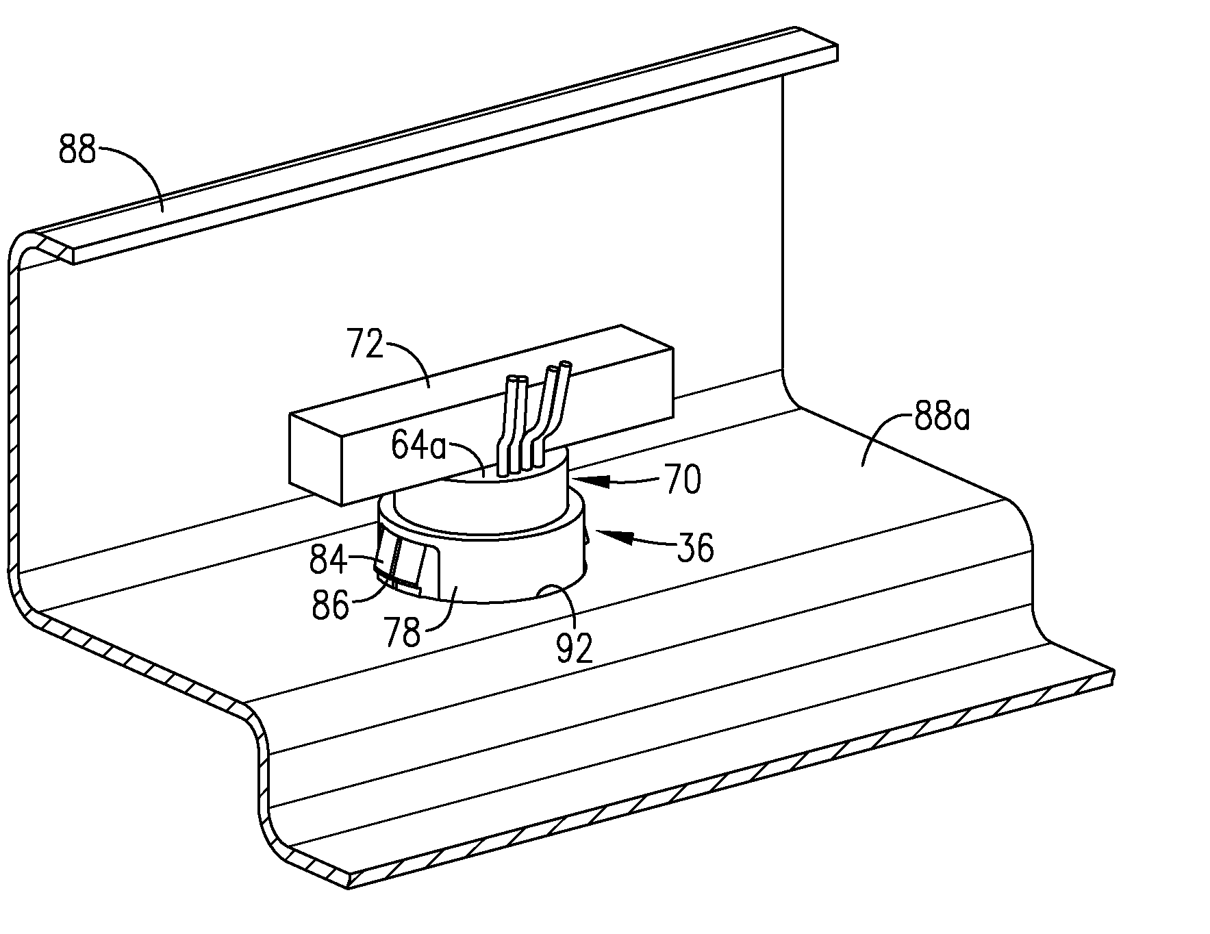
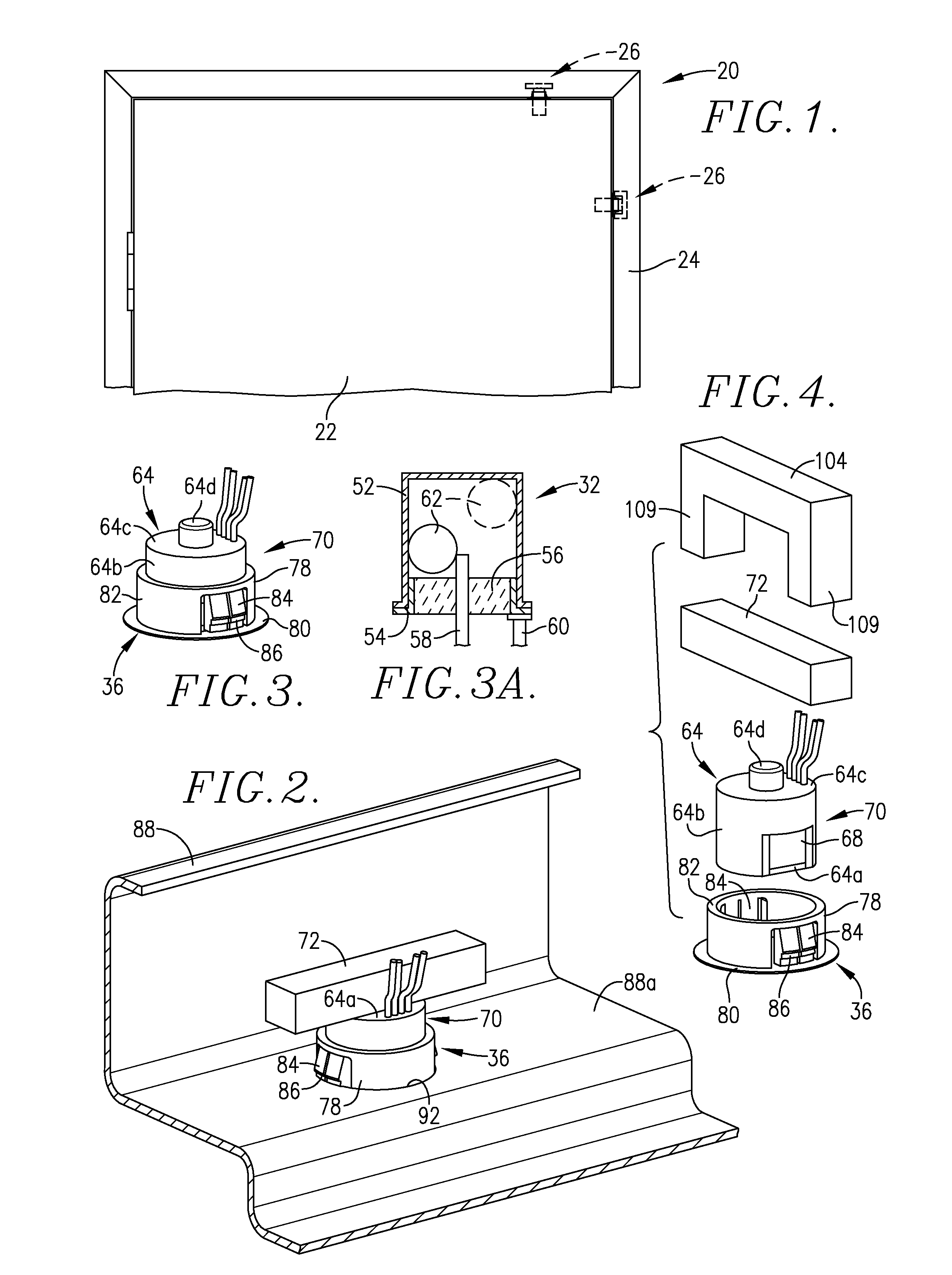
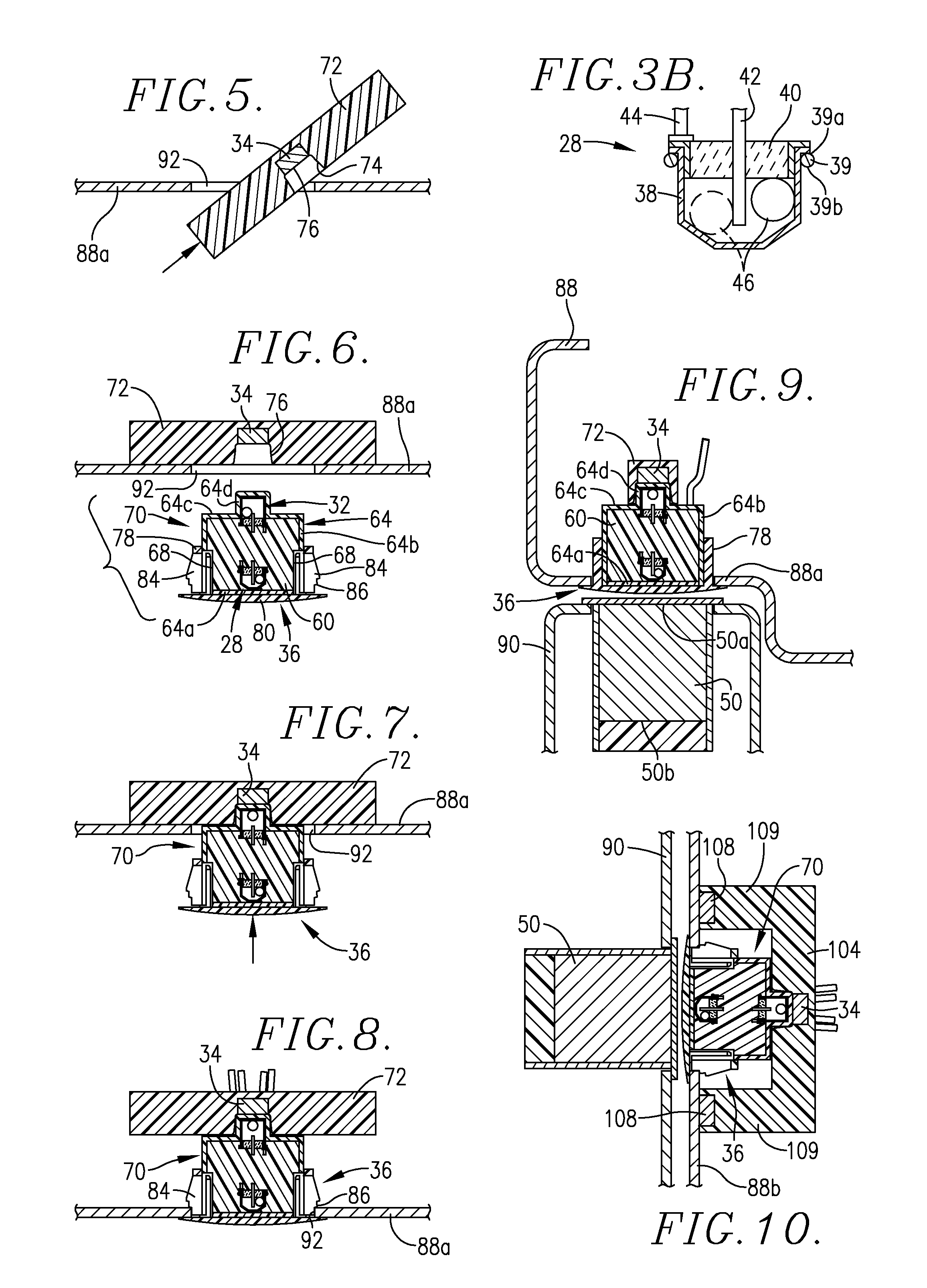
[0039]Turning now to the drawings, a protected door and door frame assembly 20 is depicted in FIG. 1 and includes a conventional door 22 and surrounding door frame 24. The assembly 20 is protected by a tamper-resistant alarm switch assembly 26, which can be mounted in the alternate top and side positions depicted in the figure. Although not shown, it will be understood that the switch assembly 26 is operably coupled with an alarm controller and alarm bell or other perceptible alarm-indicating device. A complete system of this type is illustrated in U.S. Pat. No. 7,291,794 (FIG. 3), and such system disclosure is incorporated by reference herein.
[0040]The tamper-resistant switch assemblies of the invention are similar to the switch assemblies illustrated and described in U.S. Patent Publication No. US-2010-0006408, which is incorporated by reference herein in its entirety.
[0041]The alarm switch assembly 26 includes a first movement-sensing switch 28 (FIG. 3B) and a second tamper-sensi...
PUM
Abstract
Tamper-resistant switch assemblies (26, 162) are provided including a first movement-sensing switch (28) and a second tamper-sensing switch assembly (30), the latter including a switchable component (32) and an actuating component (34). Preferably, the switch (28) and switch assembly (30) are housed within an encapsulated switch module (70, 114, 164), with the actuating component (34, 118, 138, 166) positioned above or to the side of the module (70, 114, 164). Mounting structure (36) serves to support the module (70, 114, 164) within a mounting opening (90, 112, 148) and is operable to prevent removal of the switchable component (32) and actuating component (34, 118, 138, 166) without significant relative shifting movement between the switchable component (32) and actuating component (34, 118, 138, 166). Any attempted tampering results in such relative shifting movement, thereby triggering an alarm.In another aspect, the invention provides switch apparatus (182) including a magnetic ball switch (32) with a first biasing magnetic component (194) and a second operating magnet component (196). Adjustment structure (190, 192) permits selective adjustment of the position of magnetic component (194) in order to permit tuning of the apparatus (182) so as to prevent defeat thereof by means of a defeat magnet (198) positioned between the magnet components (194, 196).
Description
BACKGROUND OF THE INVENTION[0001]1. Field of the Invention[0002]The present invention is broadly concerned with tamper-resistant switch assemblies for use in high-security contexts where it is not only necessary to detect relative movement between first and second members (e.g., a door and door frame), but also to detect any attempted tampering with the switch assemblies. More particularly, in one aspect the invention is concerned with tamper-resistant switch assemblies which include a tamper-sensing switch component and an actuating component which are relatively shiftable, as well as mounting structure operable to support the switch and actuating components and to prevent removal thereof without significant relative shifting movement which will trigger an alarm. In another aspect, the invention pertains to switch apparatus including a magnetic switch assembly which includes structure permitting fine adjustment of the position of the biasing magnetic component of the switch assembl...
Claims
Application Information
Patent Timeline
Application Date:The date an application was filed.
Publication Date:The date a patent or application was officially published.
First Publication Date:The earliest publication date of a patent with the same application number.
Issue Date:Publication date of the patent grant document.
PCT Entry Date:The Entry date of PCT National Phase.
Estimated Expiry Date:The statutory expiry date of a patent right according to the Patent Law, and it is the longest term of protection that the patent right can achieve without the termination of the patent right due to other reasons(Term extension factor has been taken into account ).
Invalid Date:Actual expiry date is based on effective date or publication date of legal transaction data of invalid patent.
Patent Type & Authority Applications(United States)