
Sound wave generator

a generator and sound technology, applied in the field of sound generators, can solve the problems of difficult to employ such a large diaphragm speaker, difficult to create a low pitch sound, difficult to employ such a large speaker, etc., and achieve the effect of low pitch sound

Inactive Publication Date: 2012-08-02
DENSO CORP
View PDF3 Cites 3 Cited by
  • Summary
  • Abstract
  • Description
  • Claims
  • Application Information

AI Technical Summary

Benefits of technology

[0008]It is an object of the present invention to provide a sound wave generator capable of generating a low pitch sound without requiring a large speaker.

Problems solved by technology

However, if there are any restrictions to loading and costs, it is difficult to employ such a speaker having a large diaphragm.
On the other hand, in a sound wave generator having a small speaker (microspeaker), it is difficult to create a low pitch sound.
In fact, it is difficult to employ a large speaker such as a woofer as the speaker for emitting the notification sound to an area outside of a vehicle due to the restriction to loading.
On the other hand, if a small speaker (microspeaker) is employed to generate the pseudo engine sound, it is difficult to include the low pitch sound having frequency of 400 Hz or less.
That is, in the vehicle approach notification apparatus, it is difficult to employ the large speaker due to the restriction to loading and thus it is difficult to generate the notification sound including the low pitch sound.

Method used


Image

  • Sound wave generator
  • Sound wave generator
  • Sound wave generator

Examples


first embodiment

[0025]A first embodiment will be described with reference to FIGS. 1 through 4B.

[0026]The vehicle approach notification apparatus is typically mounted in a vehicle that is driven by an electric motor and whose traveling sound is small. For example, the vehicle approach notification apparatus is mounted in an electric vehicle, a hybrid vehicle and the like. The vehicle approach notification apparatus emits a notification sound to an area outside of the vehicle depending on a traveling condition or when a sensor detects a human such as a pedestrian, thereby to notify a presence of the vehicle to a periphery of the vehicle.

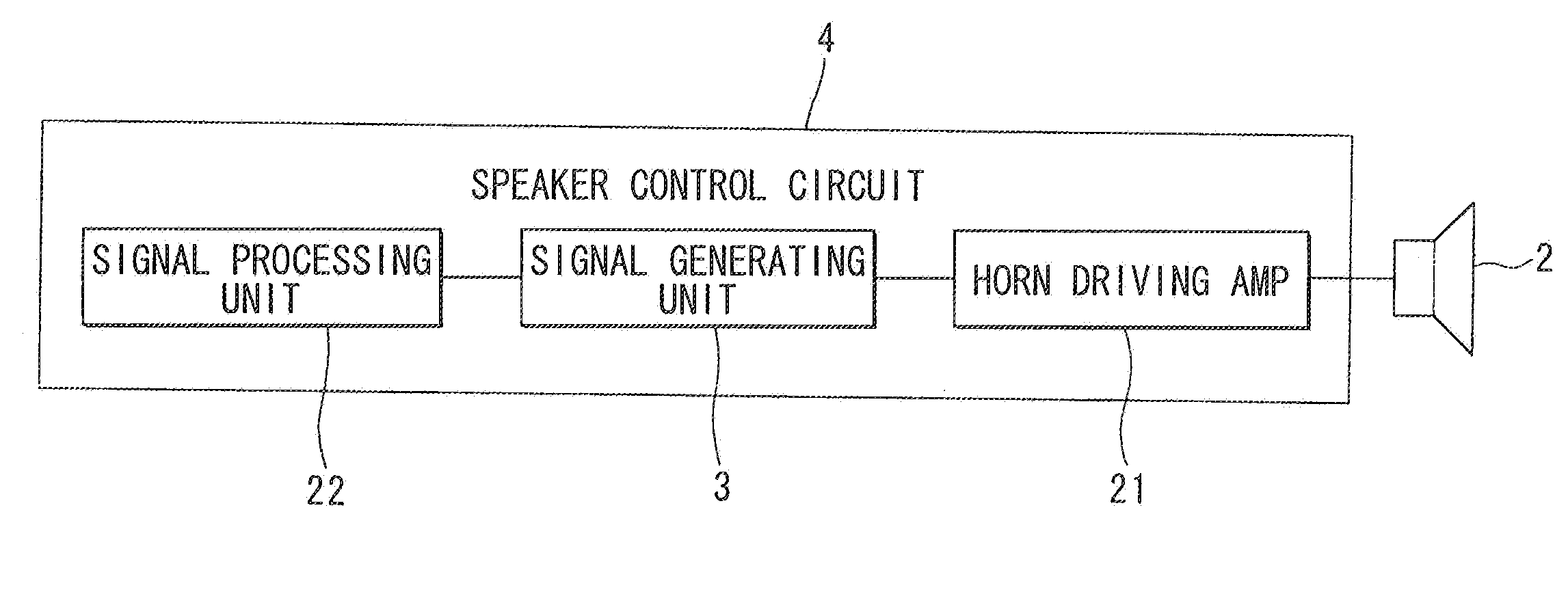
[0027]As shown in FIG. 3, the vehicle notification apparatus includes a vehicular horn 2 used as a dynamic speaker and a speaker control circuit 4 for controlling an operation of the vehicular horn 2.

[0028](Explanation of Vehicular Horn 2)

[0029]The vehicular horn 2 is an electromagnetic alarm sound generation device that emits an alarm sound to an area outside of the...

second embodiment

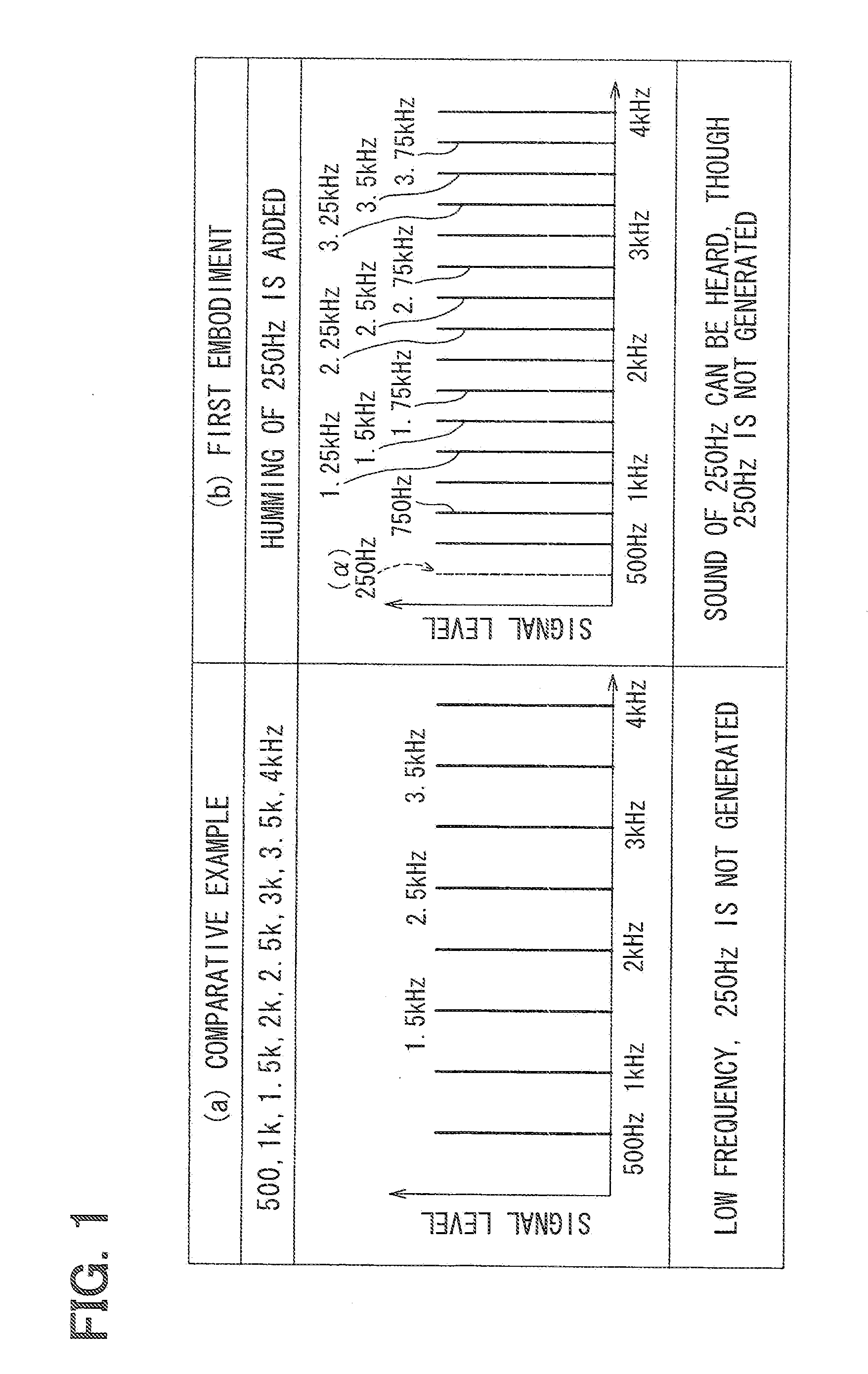
[0068]A second embodiment will be described with reference to FIGS. 5 and 6. Hereinafter, like parts are designated with like reference numerals.

[0069]The vehicular horn 2, as an example of the dynamic speaker, generates the alarm sound having the fundamental tone of 500 Hz, similar to the first embodiment. Thus, it is difficult to generate a low pitch tone (e.g., 250 Hz) lower than the fundamental tone.

[0070]Therefore, in a general technique, for example, to generate the sound of “do” of equal temperament as an example of the notification sound, a frequency signal including frequencies of “do”, which are equal to or higher than 500 Hz generated by the vehicular horn 2 (i.e., frequencies of 500 Hz, 1 kHz, 2 kHz, and 4 kHz) is used, as shown in a comparative example in (a) of FIG. 5.

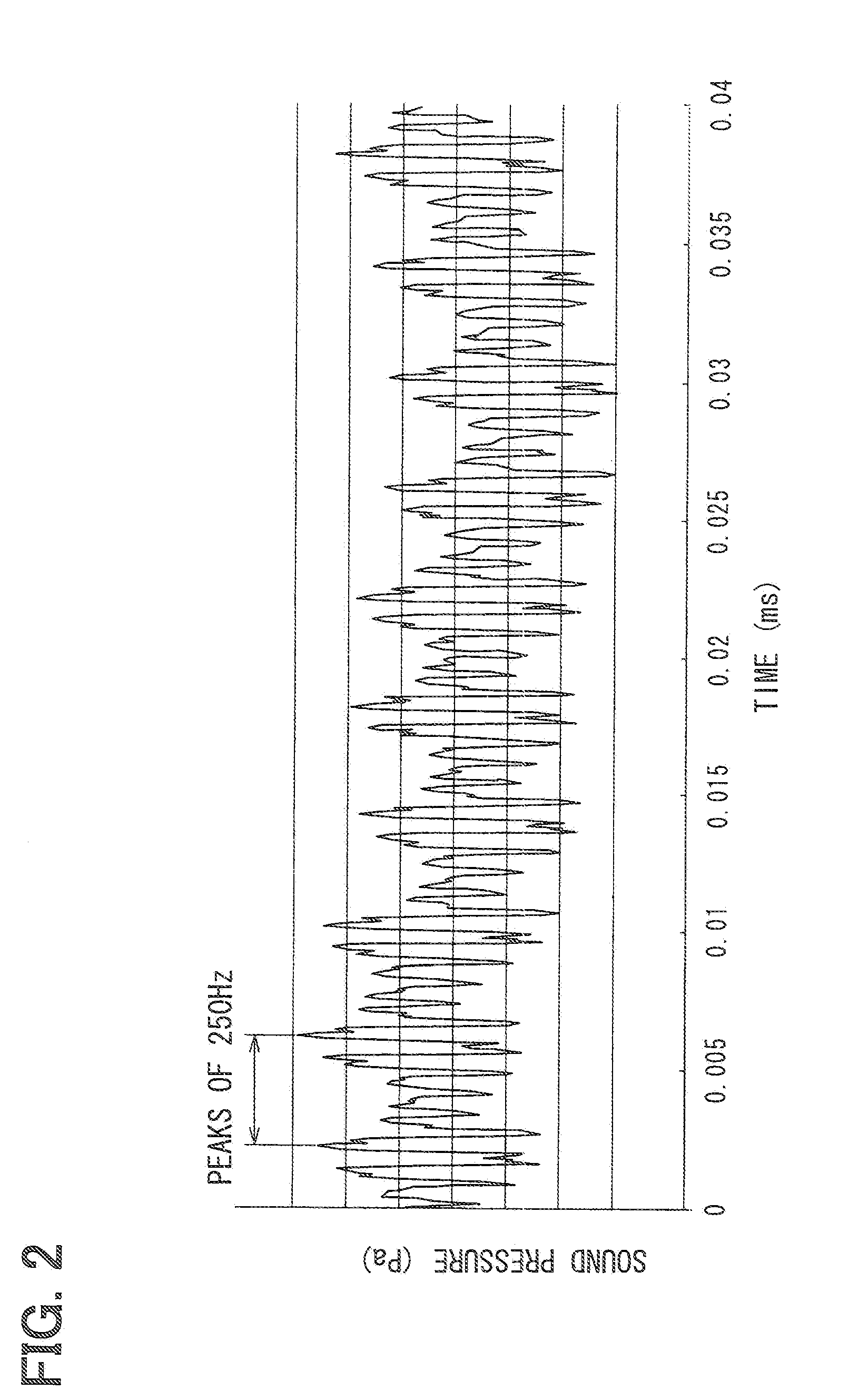
[0071]In the present embodiment, on the other hand, the target generation frequency is provided as “250 Hz (“do” sound that is in an octave lower than 500 Hz) as an example of the A Hz. Therefore, as show...


PUM


Abstract

A sound wave generator includes a speaker control circuit and a speaker. The speaker control circuit includes a signal generating unit that is configured to generate an electric signal having a humming frequency property. The humming frequency property includes a plurality of frequencies that have an overtone relationship with respect to A Hz and are pitched at the A Hz, the A Hz being a target generation frequency and corresponding to a low pitch frequency in an audible range. The speaker generates a sound wave from the electric signal by applying the electric signal to a vibration plate that produces the sound wave.

Description

CROSS REFERENCE TO RELATED APPLICATION[0001]This application is based on Japanese Patent Application No. 2011-17961 filed on Jan. 31, 2011, the disclosure of which is incorporated herein by reference.FIELD OF THE INVENTION[0002]The present invention relates to a sound wave generator.BACKGROUND OF THE INVENTION[0003]In general, a speaker having a large diaphragm, such as a woofer, is used to generate a low pitch sound. However, if there are any restrictions to loading and costs, it is difficult to employ such a speaker having a large diaphragm. On the other hand, in a sound wave generator having a small speaker (microspeaker), it is difficult to create a low pitch sound. Therefore, only a sound having less low pitch tone is generated.[0004]A sound wave generator is for example used for a vehicle approach notification apparatus for notifying a presence of a vehicle whose traveling sound is small, such as an electric vehicle, a fuel cell vehicle and a hybrid vehicle. The above drawback...

Claims


Application Information

Patent Timeline
Patent Type & Authority Applications(United States)
IPC IPC(8): B60Q1/00H04R19/02
CPCH04R3/04H04R2499/13B06B2201/70B06B2201/53B06B1/0276
Inventor NAKAYAMA, TOSHIAKIHAYASHI, TOSHIOSAKURAI, KOUJI
Owner DENSO CORP
Learn More