Speaker diaphragm, speaker, device, and method for manufacturing speaker diaphragm

a technology for speaker diaphragms and diaphragms, which is applied in the direction of transducer diaphragms, loudspeaker diaphragm shapes, instruments, etc., can solve the problems of difficult to reproduce low pitch sound, complex functions, and small size of video audio devices, so-called audio-visual equipment, etc., to reduce the supporting force of suspension, improve the linearity of suspension, and improve the effect of low pitch sound

Active Publication Date: 2016-01-14
PANASONIC INTELLECTUAL PROPERTY MANAGEMENT CO LTD
View PDF0 Cites 22 Cited by
  • Summary
  • Abstract
  • Description
  • Claims
  • Application Information

AI Technical Summary

Benefits of technology

[0012]According to this arrangement, the first holes and the second holes provided in the top surface member and the rear surface member respectively open and close when the vibrator vibrates. This allows the top surface member and the rear surface member that constitute the suspension to smoothly stretch and contract in a circumferential direction. The intermediate member is designed to have a rigidity lower than that of the top surface member and the rear surface member to an extent such that opening and closing of the holes are not inhibited. As a result, linearity of the suspension improves. Furthermore, since the suspension smoothly moves due to opening and closing of the holes, it is possible to reduce the supporting force of the suspension in the amplitude direction of the vibrator. It is therefore possible to realize a speaker diaphragm that is capable o

Problems solved by technology

In recent years, video audio devices, so-called audio-visual equipment, are rapidly becoming smaller and their functions are rapidly becoming more complex.
This make

Method used


Image

  • Speaker diaphragm, speaker, device, and method for manufacturing speaker diaphragm
  • Speaker diaphragm, speaker, device, and method for manufacturing speaker diaphragm
  • Speaker diaphragm, speaker, device, and method for manufacturing speaker diaphragm

Examples


first embodiment

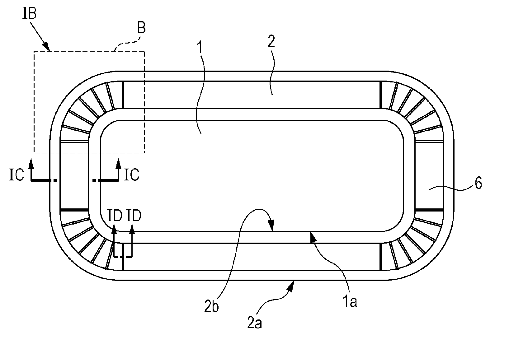
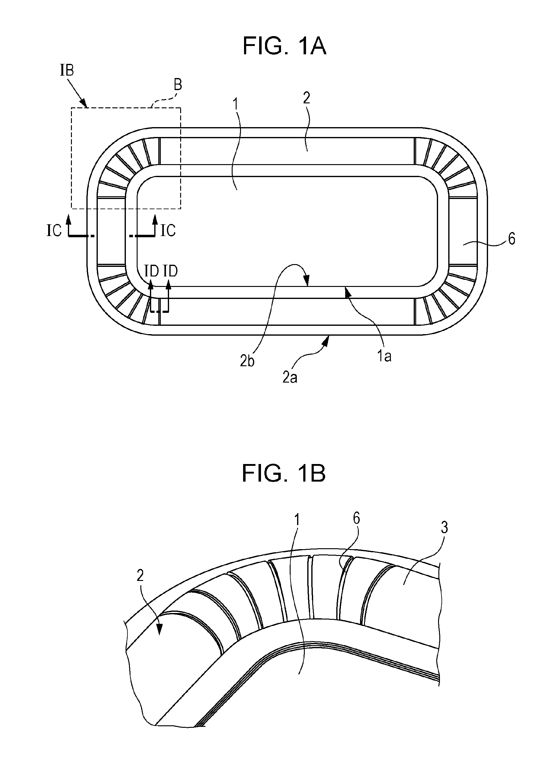
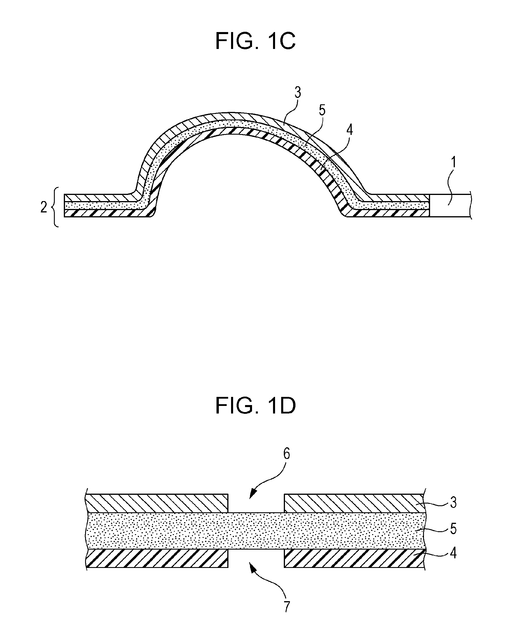
[0116]FIG. 1A is a top view of a speaker diaphragm according to the First Embodiment of the present disclosure. FIG. 1B is a perspective view for explaining a structure of the part IB indicated by the dotted line in FIG. 1A. FIG. 1C is a cross-sectional view taken along the line IC-IC in FIG. 1A. FIG. 1D is a cross-sectional view taken along the line ID-ID in FIG. 1A.

Configuration of Speaker Diaphragm

[0117]First, an example of a configuration of a speaker diaphragm according to the First Embodiment of the present disclosure is described. The speaker diaphragm according to the First Embodiment illustrated in FIGS. 1A through 1D includes a vibrator 1 (also referred to as a diaphragm 1) and a suspension 2.

[0118]The vibrator 1 has an outer peripheral part 1a that has, for example, a circular shape, an elliptic shape, a polygonal shape, or a shape combining two or more straight lines and two or more curves. For example, the outer peripheral part 1a has a so-called running track shape con...

application example

[0133]Some application examples using the speaker diaphragm according to the First Embodiment described above are described with reference to FIGS. 3A through 3E.

[0134]FIG. 3A illustrates a structure in which a sealing member 9 is provided so as to cover the first holes 6 of the top surface member 3. In a case where a speaker is mounted on a cabinet, a force according to acoustic compliance of the cabinet sometimes works on the suspension 2 during driving of the speaker. Furthermore, the intermediate member 5 is subject to repeated stresses in accordance with opening and closing of the first holes 6 and the second holes 7 caused by vibration of the vibrator 1. The configuration of this application example is for reinforcing the intermediate member 5 by using the sealing member 9 so that the intermediate member 5 has sufficient strength against the stresses.

[0135]According to this structure, the sealing member 9 is provided so as to fill the first holes 6. That is, the sealing member...

second embodiment

[0139]FIG. 4A is a top view of a speaker diaphragm according to the Second Embodiment of the present disclosure. FIG. 4B is a perspective view for explaining a structure of the part IVB indicated by the dotted line in FIG. 4A. FIG. 4C is a cross-sectional view taken along the line IVC-IVC in FIG. 4A. FIG. 4D is a cross-sectional view taken along the line IVD-IVD in FIG. 4A.

Configuration of Speaker Diaphragm

[0140]First, the configuration of the speaker diaphragm according to the Second Embodiment of the present disclosure is described. The speaker diaphragm according to the Second Embodiment illustrated in FIGS. 4A through 4D includes a vibrator 1, a suspension 2, and a sealing member 9.

[0141]The vibrator 1 has an outer peripheral part 1a that has, for example, a circular shape, an elliptic shape, a polygonal shape, or a shape combining two or more straight lines and two or more curves. The vibrator 1 illustrated in FIG. 4A has a substantially rectangular shape constituted by four st...


PUM


Abstract

A speaker diaphragm includes: a vibrator; and a suspension adhered to an outer peripheral part of the vibrator and supporting the vibrator so that the vibrator can vibrate, at least part of the suspension including a top surface member constituting a top surface part of the suspension, a rear surface member constituting a rear surface part of the suspension, and an intermediate member between the top surface member and the rear surface member, these members being stacked, the intermediate member having a rigidity lower than that of at least one of the top surface member and the rear surface member, the top surface member having one or more first holes, the rear surface member having one or more second holes, and at least some of the first holes and second holes being dispose so as to overlap across the intermediate member in a direction in which the members are stacked.

Description

BACKGROUND[0001]1. Technical Field[0002]The present disclosure relates to a speaker diaphragm, a speaker including a speaker diaphragm, a device including a speaker, and a method for manufacturing a speaker diaphragm. More specifically, the speaker and the device of the present disclosure relate to a small speaker that is capable of reproducing broadband sound, a video audio device including the speaker (a video display appliance, an audio appliance, an in-ear headphone, a home electrical appliance, and the like), a mobile information processing device (a mobile phone, a smartphone, a tablet PC, an operation terminal, and the like), and a moving device (an automobile, a railroad, and the like).[0003]2. Description of the Related Art[0004]In recent years, video audio devices, so-called audio-visual equipment, are rapidly becoming smaller and their functions are rapidly becoming more complex. This trend is marked especially in mobile phones, smartphones, tablet PC (personal computer) ...

Claims


Application Information

Patent Timeline
IPC IPC(8): H04R7/16H04R31/00
CPCH04R31/003H04R7/16H04R7/18H04R2307/204H04R2307/207H04R2499/11H04R2499/13
Inventor MATSUMURA, TOSHIYUKISAIKI, SHUJI
Owner PANASONIC INTELLECTUAL PROPERTY MANAGEMENT CO LTD
Why Eureka
Try Eureka