Coupling systems

a coupling system and coupling technology, applied in the direction of snap fasteners, buckles, mechanical equipment, etc., can solve the problems of low durability and low weight of the releasable coupling system for optimal performance, the conventional releasable coupling system including the molle system does not optimize the performance characteristics of retail applications, and the releasable coupling system on outdoor backpacks requires both high durability and low weight for optimal performance. , to achieve the effect o

Active Publication Date: 2012-08-09
WORKSHOP XI
View PDF5 Cites 4 Cited by
  • Summary
  • Abstract
  • Description
  • Claims
  • Application Information

AI Technical Summary

Benefits of technology

[0007]Embodiments of the present invention represent a significant advance in the field of releasable coupling systems. Conventional releasable coupling systems fail to provide all of the performance characteristics of the present invention, including but not limited to modularity, intuitive operation, maximum durability, and minimum weight. In particular, embodiments of the present invention may be used to couple a buckle to a base. The base may be a soft good member such as a garment, carrying device, or load bearing strap. The system may be used for releasable coupling of an individual location such as the releasable closure of a pocket or pouch. The system may also be used as a modular coupling system to facilitate multiple releasable coupling locations. In contrast to many releasable coupling systems (i.e. VELCRO, snap locks, etc.) embodiments of the present invention provide durable releasable coupling that is resistant to incidental compression forces and / or debris accumulation. In addition, components of the present invention are capable of being efficiently manufactured.

Problems solved by technology

For example, releasable coupling systems on outdoor backpacks require both high durability and low weight for optimal performance.
Conventional releasable coupling systems fail to provide optimal performance characteristics for use as a modular soft good releasable coupling system.
Unfortunately, conventional modular releasable coupling systems including the MOLLE system do not optimize performance characteristics for retail applications.
For example, the MOLLE system requires numerous unattractive horizontal straps for intercoupling components.
In addition, the MOLLE system and other modular systems require a non-intuitive complex coupling method.

Method used


Image

  • Coupling systems
  • Coupling systems
  • Coupling systems

Examples


Embodiment Construction

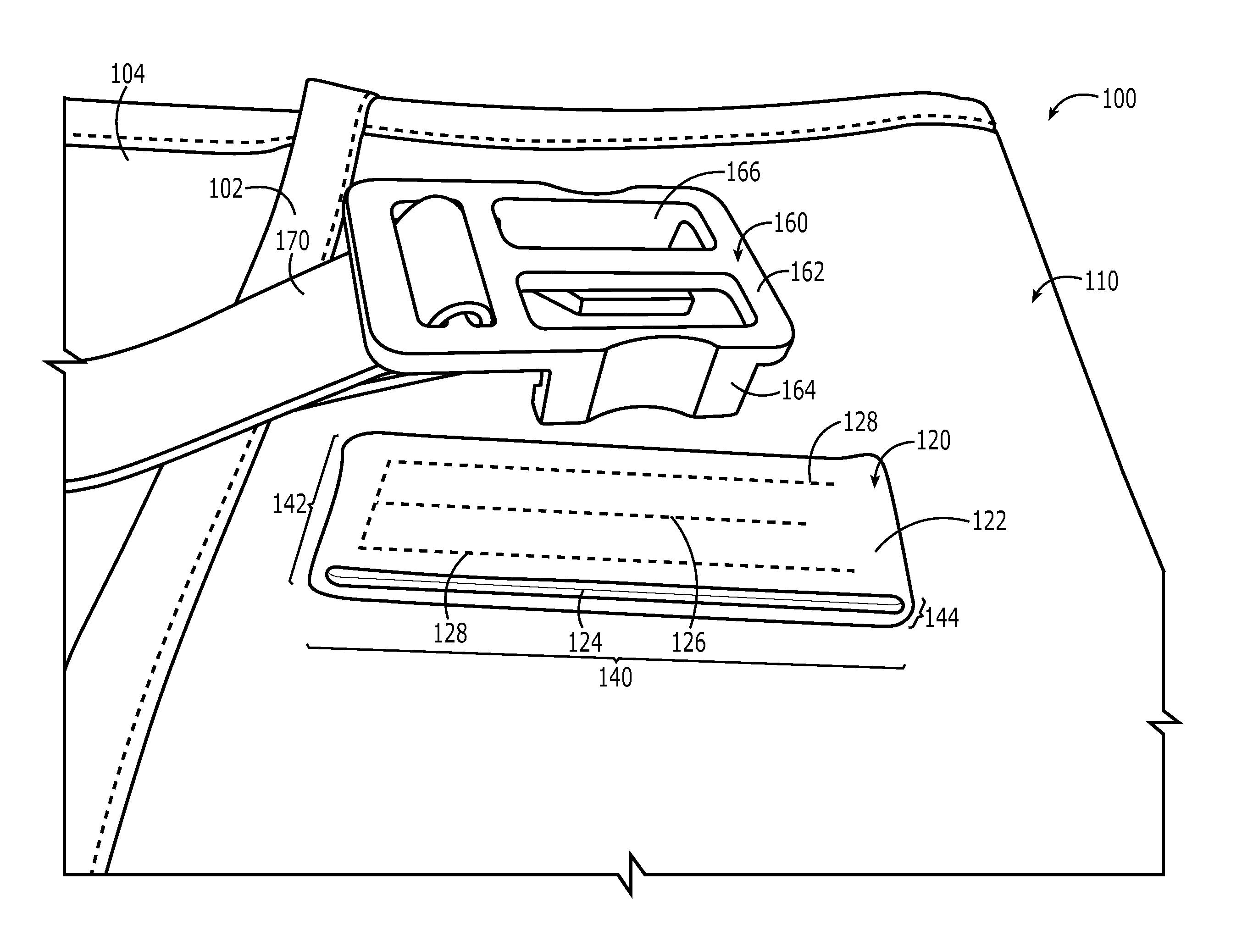
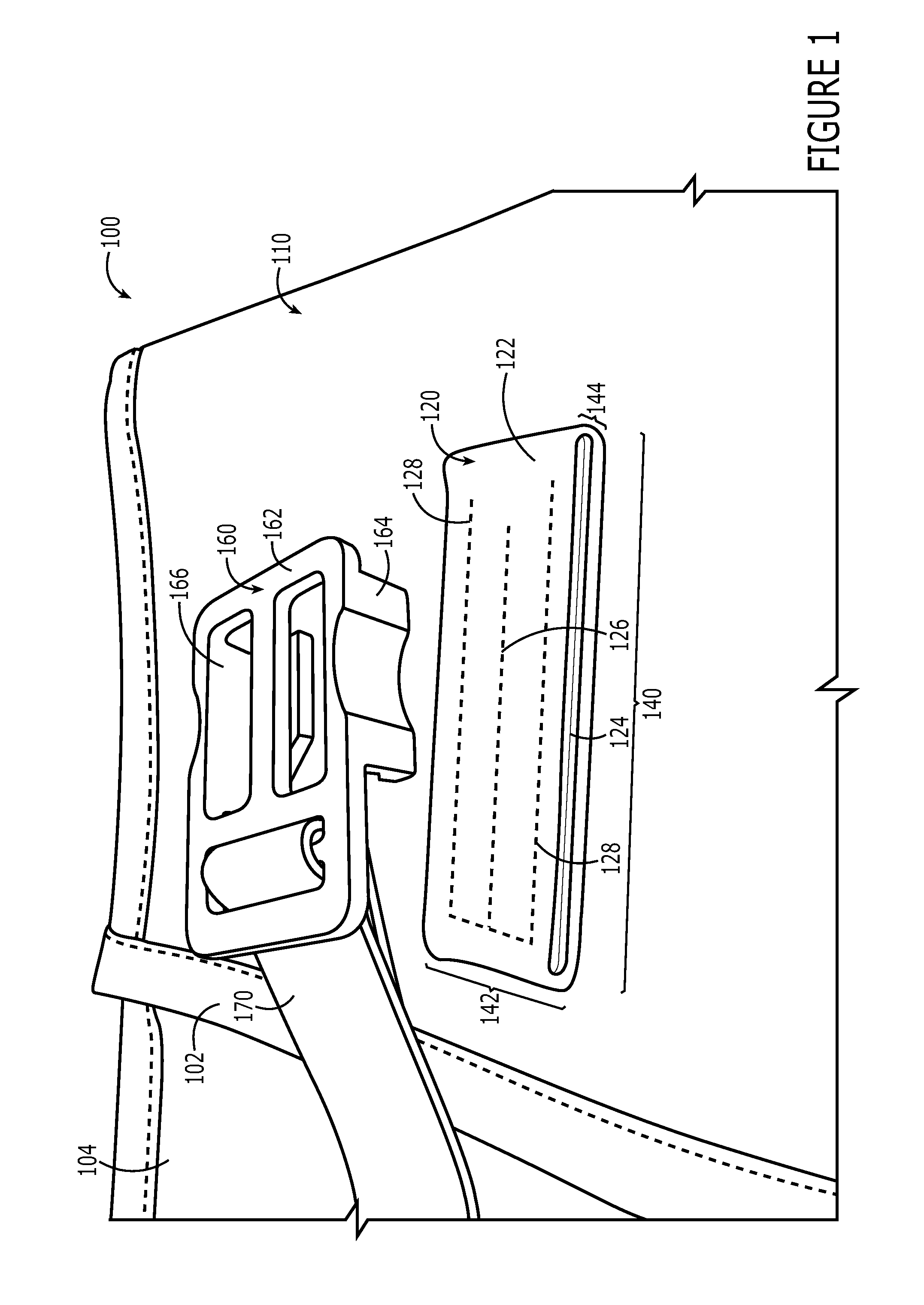
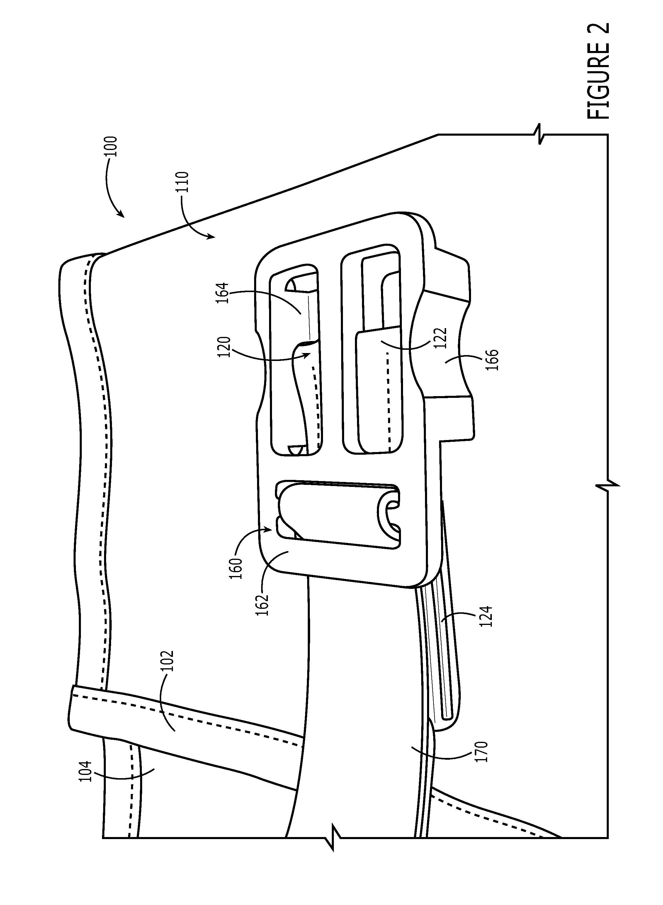
[0022]The present invention relates to improved coupling systems. One embodiment of the present invention relates to a releasable coupling system comprising a base, a lengthwise member, and a buckle. The lengthwise member is fixably coupled to the base parallel to the lengthwise dimension and substantially medial with respect to the widthwise dimension. The buckle comprises a planar surface and a first and second hooked region extending from the planar surface oriented opposite one another. The first and second hooked regions and the planar surface define a partially enclosed region corresponding to the widthwise dimension and the base rise dimension of the lengthwise member. A gap in the partially enclosed region corresponds to a coupling between the lengthwise member and the base. A second embodiment of the present invention relates to a method for releasably coupling a buckle to a base comprising the acts of providing a base, a lengthwise member, and a buckle; coupling the length...


PUM


Abstract

One embodiment of the present invention relates to a releasable coupling system comprising a base, a lengthwise member, and a buckle. The lengthwise member is fixably coupled to the base parallel to the lengthwise dimension and substantially medial with respect to the widthwise dimension. The buckle comprises a planar surface and a first and second hooked region extending from the planar surface oriented opposite one another. The first and second hooked regions and the planar surface define a partially enclosed region corresponding to the widthwise dimension and the base rise dimension of the lengthwise member. A gap in the partially enclosed region corresponds to a coupling between the lengthwise member and the base.

Description

FIELD OF THE INVENTION[0001]The invention generally relates to improved coupling systems. In particular, the present invention relates to a releasable modular coupling system and methods of operation.BACKGROUND OF THE INVENTION[0002]Coupling systems attach members / components to one another. One type of coupling system is a releasable coupling system that enables a user to repeatedly couple or decouple members from one another. For example, a conventional automobile seatbelt is a releasable coupling system which may be used to secure a passenger in a particular seat. Likewise, a belt is a releasable coupling system for securing pants around a user's waist. Releasable coupling systems include multiple components which are coupled together. An automobile seatbelt includes at least two straps and two intercoupling buckles. Likewise, a belt includes a strap and a buckle.[0003]Releasable coupling systems may be used for a variety of applications, each corresponding to a hierarchy of optim...

Claims


Application Information

Patent Timeline
Patent Type & Authority Applications(United States)
IPC IPC(8): A44B11/25F16B45/00
CPCY10T24/4736A44B11/258A45F5/02Y10T24/4745Y10T24/4093A41D2400/48Y10T24/45969
Inventor FALVAI, MARK
Owner WORKSHOP XI
Why Eureka
Try Eureka