

Wireless power feeder and wireless power transmission system
a technology of wireless transmission system and wireless power feeder, which is applied in the direction of basic electric elements, transformers/inductance circuits, inductances, etc., can solve the problem of not being able to feed big electric power
- Summary
- Abstract
- Description
- Claims
- Application Information
AI Technical Summary
Benefits of technology
Problems solved by technology
Method used
Image

Examples
first embodiment
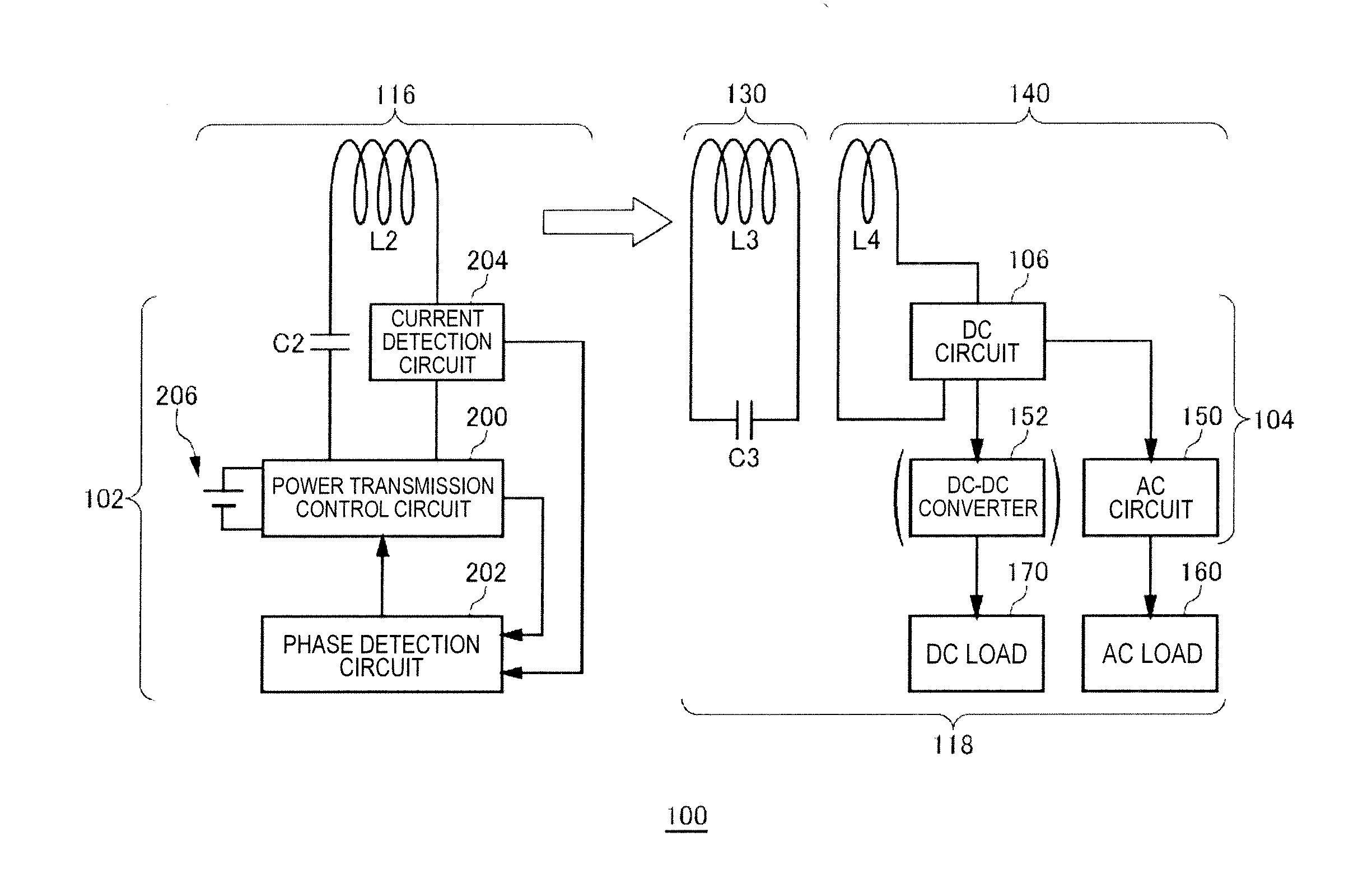
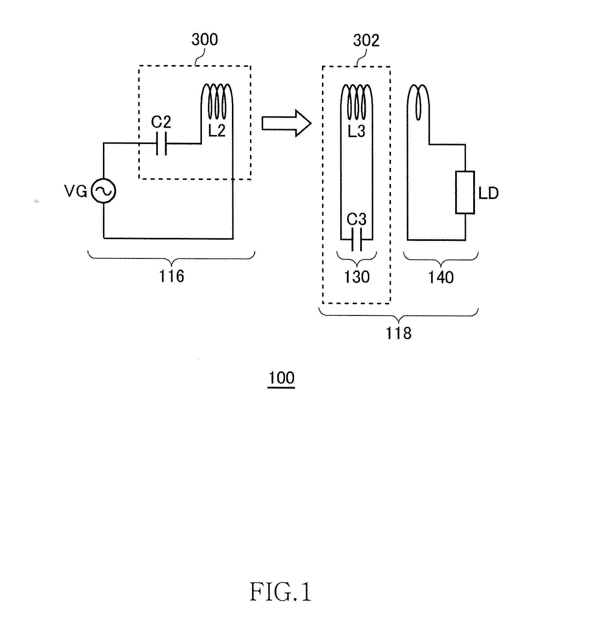
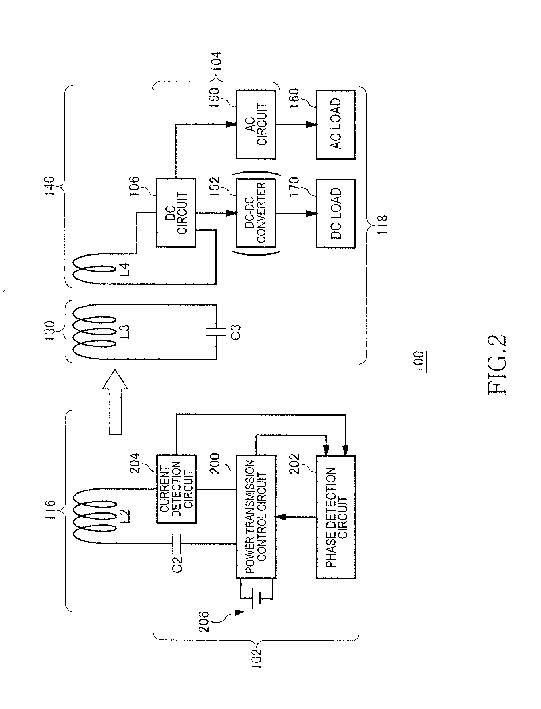
[0041]FIG. 1 is a view illustrating operation principle of a wireless power transmission system 100 according to a first embodiment. The wireless power transmission system 100 of the first embodiment includes a wireless power feeder 116 and a wireless power receiver 118. The wireless power feeder 116 includes a power feeding LC resonance circuit 300. The wireless power receiver 118 includes a receiving coil circuit 130 and a loading circuit 140. A power receiving LC resonance circuit 302 is formed by the receiving coil circuit 130.
[0042]The power feeding LC resonance circuit 300 includes a capacitor C2 and a feeding coil L2. The power receiving LC resonance circuit 302 includes a capacitor C3 and a receiving coil L3. The values of the capacitor C2, power feeding coil L2, capacitor C3, and power receiving coil L3 are set such that the resonance frequencies of the power feeding LC resonance circuit 300 and power receiving LC resonance circuit 302 coincide with each other in a state wh...
second embodiment
[0081]FIG. 10 is a schematic view of the wireless power transmission system 100 in a second embodiment. In the wireless power transmission system 100 in the second embodiment, a plurality of wireless power receivers 118a and 118b are related to the single wireless power feeder 116. The wireless power receiver 118a is so called a “DC type” wireless power receiver 118 that converts AC power into DC power by means of the DC circuit 106 and supplies the DC load 170 with the DC power. The wireless power receiver 118b is so called an “AC type” wireless power receiver 118 that supplies the AC load 160 with AC power generated by means of the DC circuit 106 and AC circuit 150. Power may be fed to the AC load 160 and DC load 170 simultaneously or selectively by the combination use of the DC type wireless power receiver 118a and AC type wireless power receiver 118b.
third embodiment
[0082]FIG. 11 illustrates an application example of the wireless power transmission system 100 in a third embodiment. Some of the DC power generated by the solar cell 142 is supplied to the EV 158 through the same path as illustrated in FIG. 9. Some of DC power is once drawn indoors by wire and then supplied to the DC loads 170a to 170e by wireless power feeding. In the third embodiment, a pair of the wireless power feeder 116 and wireless power receiver 118 is provided for each of the DC loads 170a to 170e. Further, some of the DC power generated by the solar cell 142 is converted into AC power of a predetermined frequency by the AC circuit 120. The AC circuit 120 is a common DC-AC converter. The AC power generated by the AC circuit 120 is supplied to the AC loads 160a to 160c through indoor wirings.
[0083]In the third embodiment, the DC power and AC power are generated from the solar cell 142 (DC power supply 206) and are simultaneously supplied to the indoor wirings. As described ...
PUM
 Abstract
Description
Claims
Application Information