
Imaging and projecting devices and methods

a projector and projector technology, applied in the field of imaging, can solve the problems of reducing the amount of light received by the film or the sensor, and it is impossible to achieve large dofs with standard lenses

Inactive Publication Date: 2012-08-09
BRONSTEIN BRONSTEIN KIMMEL TECH
View PDF6 Cites 82 Cited by
  • Summary
  • Abstract
  • Description
  • Claims
  • Application Information

AI Technical Summary

Benefits of technology

[0019]Furthermore, in accordance with embodiments of the present invention, a tilting angle of each of the reorientable mirrors may be modifiable, so as to allow increasing or decreasing the tilting angle.

Problems solved by technology

However, small apertures reduce the amount of light received by the film or the sensor, so it is impractical to achieve large DOFs with standard lenses.

Method used


Image

  • Imaging and projecting devices and methods
  • Imaging and projecting devices and methods
  • Imaging and projecting devices and methods

Examples


Embodiment Construction

[0040]Light field is a function that describes the amount of light traveling in every direction through every point in space, and can be parameterized by five parameters (point coordinates x,y,z+direction φ,θ), resulting in a five-dimensional (5D) function L(x,y,z,φ,θ;λ), where L represents light intensity from x,y,z in the direction φ,θ at wavelength λ (which is considered here as a parameter rather than additional sixth dimension of the light field). In what follows, we will omit the dependence on the wavelength whenever possible.

[0041]Assuming no occlusions or optical interferences are present in space, the amount of light along each direction φ,θ is the same. Thus, the five dimensional representation of the light field function is redundant, and effectively the light field can be described by four parameters, for example, by parametrizing two planes u,v and s,t (u.v being a position coordinate in one plane and s,t being a position coordinate in the other plane).

[0042]A plenoptic...


PUM


Abstract

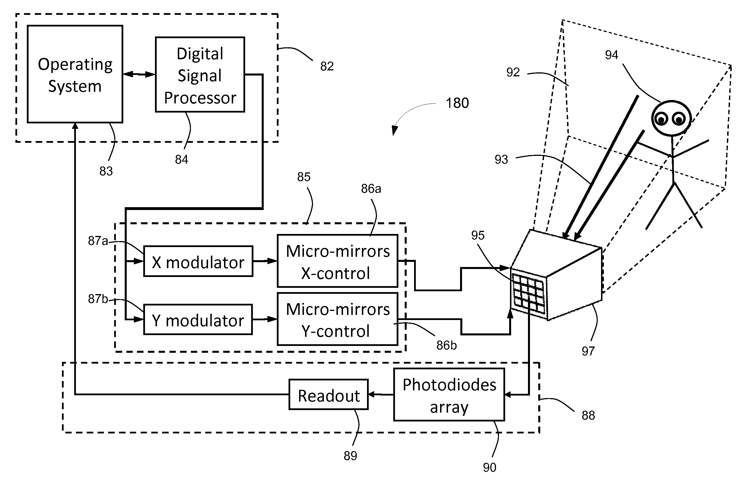
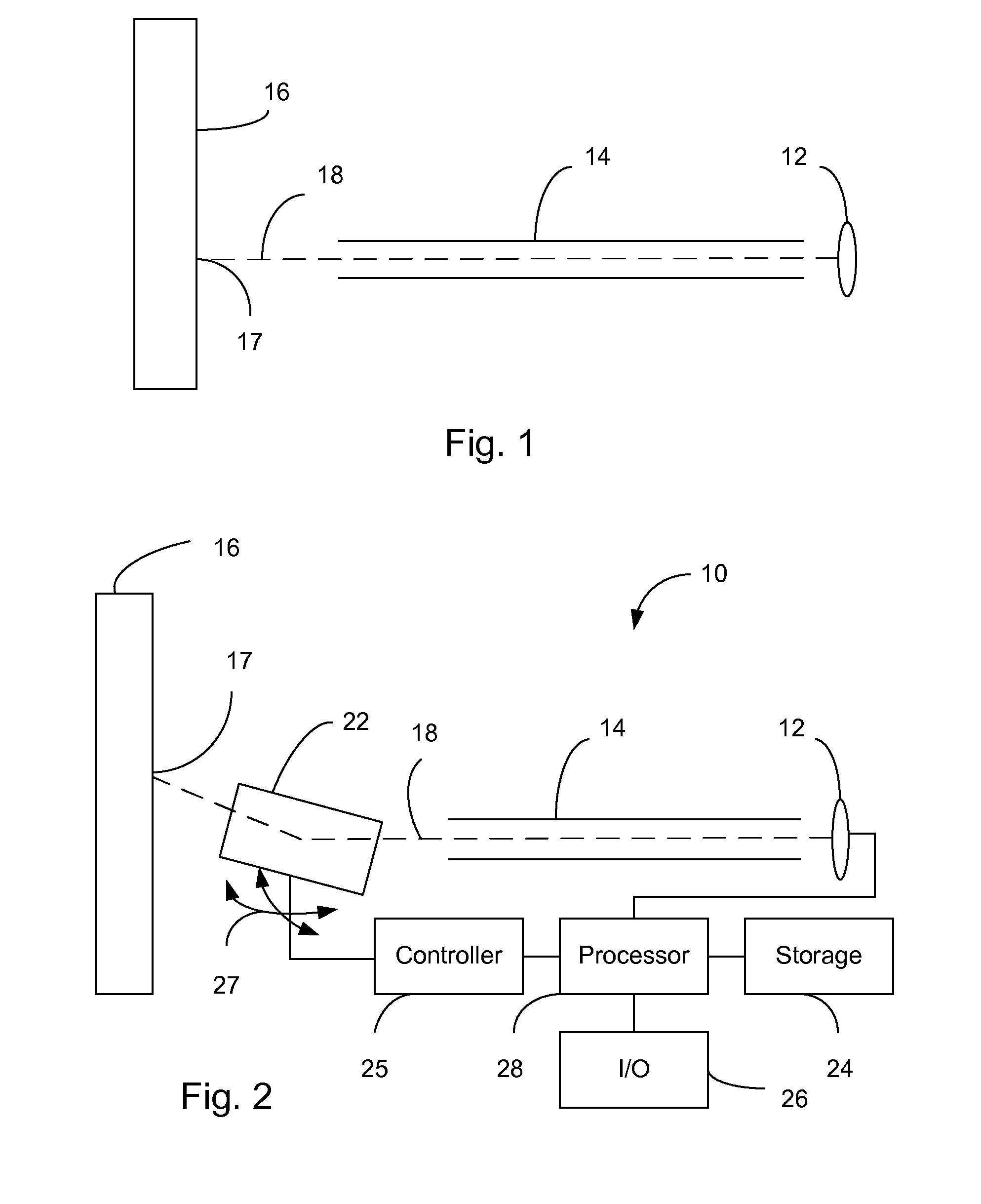
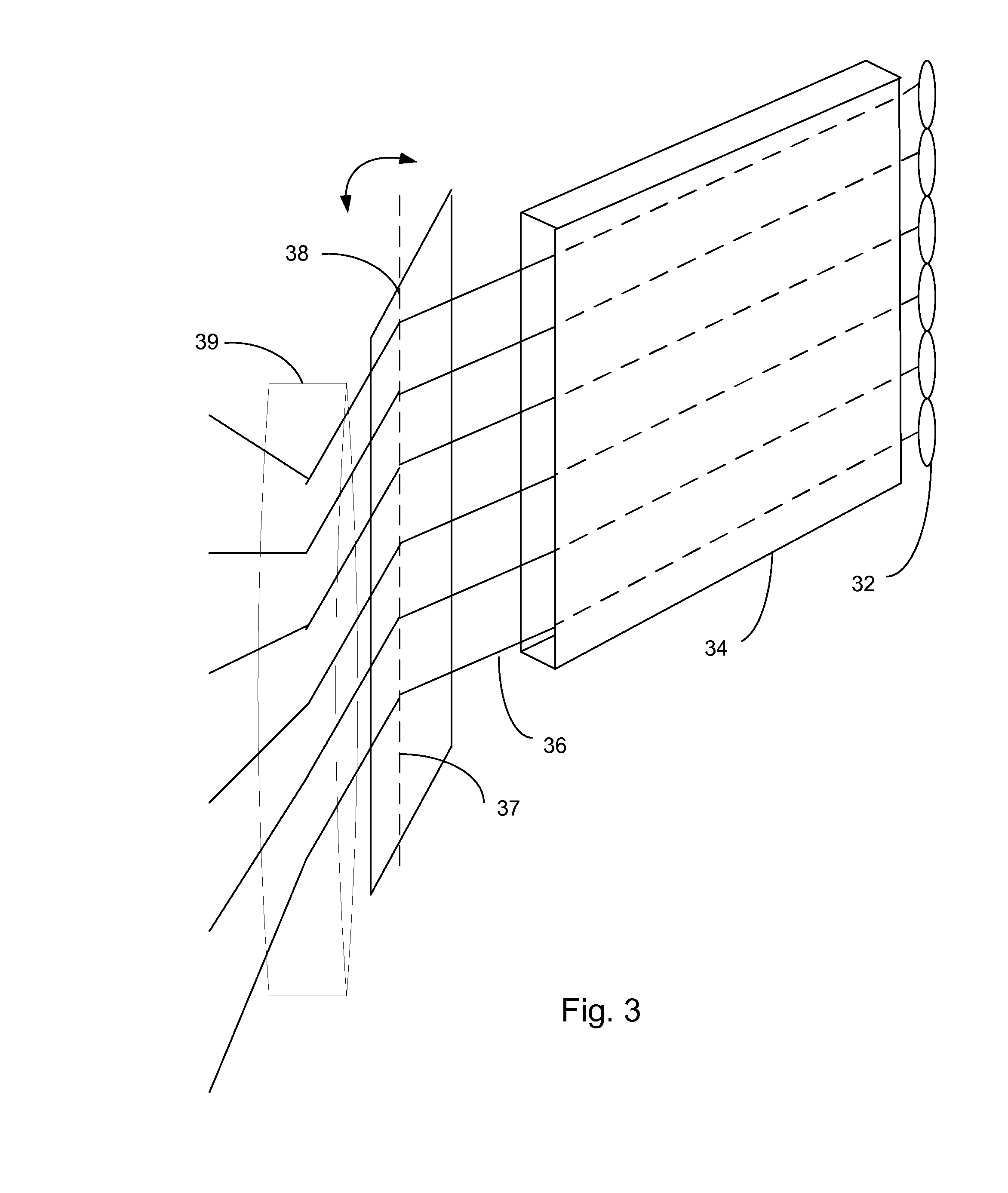
An imaging device is disclosed which may include at least one single pixel imaging sensor configured to sense image data for a single pixel along a line of sight. The imaging device may also include at least one reorientable mirror, of which each reorientable mirror is exclusively optically coupled to one or more of said at least one single pixel imaging sensor for deflecting the line of sight of that single pixel imaging sensor. The imaging device may further include a controller for synchronously reorienting each of said at least one reorientable mirror to scan the line of sight across at least a sector of a scene. The imaging device may also include a readout circuit for reading out acquired image data from each of said at least one single pixel imaging sensor. The imaging device may be configured to sample at least two independent dimensions of a four dimensional light field. A plenoptic imaging device and a plenoptic projector device are also disclosed.

Description

PRIOR APPLICATION DATA[0001]The present application claims priority from prior provisional application 61 / 302,353 filed Feb. 8, 2010, incorporated herein by reference in its entirety.FIELD OF THE INVENTION[0002]The present invention relates to imaging. More specifically, the present invention relates to imaging and projecting devices and methods.BACKGROUND[0003]Standard lenses used in cameras and imaging and projection devices may typically focus only at a limited range of distances. Objects located at other distances from the lens will appear blurred. In practice, the decrease in sharpness is gradual on either side of the focused distance, and the interval of distances within which the degraded sharpness is imperceptible under normal viewing conditions is referred to as the Depth Of Field (DOF).[0004]DOF is inversely proportional to the lens aperture diameter. Decreasing the aperture size, a lens is effectively turned into a pencil beam collimator, which in the limit has an infinit...

Claims


Application Information

Patent Timeline
Patent Type & Authority Applications(United States)
IPC IPC(8): G02B27/22H04N5/225H04N13/363
CPCG02B26/0833G02B27/2271H04N13/0427H04N13/0459H04N5/2254H04N13/365H04N13/363G02B30/50H04N23/957
Inventor BRONSTEIN, ALEXANDERBRONSTEIN, MICHAELKIMMEL, RON
Owner BRONSTEIN BRONSTEIN KIMMEL TECH
Learn More