Designated forwarder election for vpls with bgp-based mac learning

a technology of vpls and mac learning, applied in the field of designated forwarder election in a communication network, can solve the problems of failure of the link between a pe device and a corresponding ce device, and the failure of each pe devi

Active Publication Date: 2012-08-09
CISCO TECH INC
View PDF4 Cites 74 Cited by
  • Summary
  • Abstract
  • Description
  • Claims
  • Application Information

AI Technical Summary

Problems solved by technology

Unfortunately, each PE device is subject to failure.
Similarly, a link between a PE device and a corresponding CE device could fail.

Method used


Image

  • Designated forwarder election for vpls with bgp-based mac learning
  • Designated forwarder election for vpls with bgp-based mac learning
  • Designated forwarder election for vpls with bgp-based mac learning

Examples


specific example embodiments

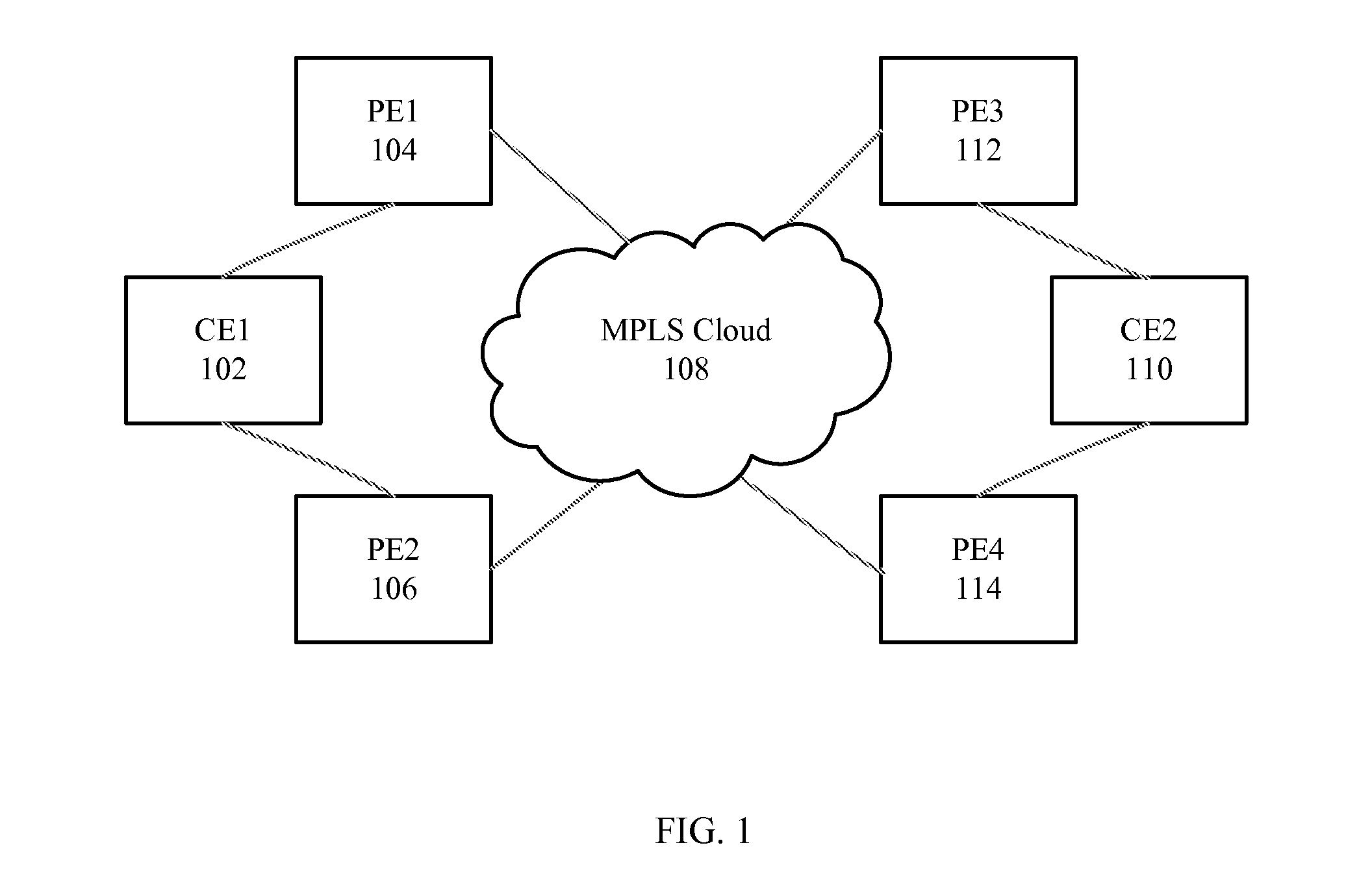
[0015]Multi-homing is one possible solution for providing node, link and port redundancy for Service Providers offering Layer 2 Virtual Private Network (VPN) services. For example, Virtual Private LAN Switching (VPLS) multihoming enables a customer site (e.g., customer network) to be connected to multiple PE devices (e.g., routers). Each customer site may be associated with one of a plurality of customers. Each of the customers may have associated therewith one or more customer sites. Therefore, any two customer sites may be associated with the same customer or different customers. A customer may be an entity such as a business, company, organization, or individual.

[0016]For example, as shown in FIG. 1, a first customer site may be connected via a first CE device, CE1102, to two PE devices, PE1104 and PE2106. The two PE devices, PE1104 and PE2106, may be connected to a core 108 of a Service Provider network such as a Multi-Protocol Label Switching (MPLS) core. Similarly, a second cu...


PUM


Abstract

In one embodiment, a network device may participate in an election process to elect one of two or more Provider Edge devices of a Redundancy Group to be a Designated Forwarder for the Redundancy Group, where the Redundancy Group is in a Service Provider network, and where the Redundancy Group serves a Customer Edge device of a customer network. The network device may forward multi-destination traffic to the Customer Edge device according to whether the network device is elected to be the Designated Forwarder for the Redundancy Group. Multi-destination traffic may include multicast traffic, broadcast traffic, or destination unknown unicast traffic.

Description

BACKGROUND[0001]1. Technical Field[0002]The present disclosure relates generally to the election of a Designated Forwarder in a communication network and more particularly, to the election of a Designated Forwarder on a per-Redundancy Group basis.[0003]2. Description of the Related Art[0004]A Service Provider network typically provides service to customer networks via Provider Edge (PE) devices (e.g., routers) at the edge of the Service Provider network. More particularly, each PE device may be connected to a Customer Edge (CE) device (e.g., router) at the edge of a customer network.[0005]Unfortunately, each PE device is subject to failure. Similarly, a link between a PE device and a corresponding CE device could fail. As a result, it is desirable to build redundancy into the Service Provider network.BRIEF DESCRIPTION OF THE DRAWINGS[0006]FIG. 1 is a diagram illustrating an example system supporting multi-homing in which various embodiments may be implemented.[0007]FIG. 2 is a diagr...

Claims


Application Information

Patent Timeline
Patent Type & Authority Applications(United States)
IPC IPC(8): H04L12/56H04L45/28
CPCH04L45/28H04L45/04
Inventor MARQUES, PEDRO MIGUEL MARTINS ROQUESAJASSI, ALISALAM, SAMERPATEL, KEYUR
Owner CISCO TECH INC
Why Eureka
Try Eureka