Image forming apparatus capable of reducing image density irregularity

a technology of image density and forming apparatus, which is applied in the direction of electrographic process apparatus, instruments, optics, etc., can solve the problems that the density irregularity cannot be reduced appropriately, and the density irregularity cannot be completely reduced across multiple different types of images

Active Publication Date: 2012-08-09
RICOH KK
View PDF10 Cites 43 Cited by
  • Summary
  • Abstract
  • Description
  • Claims
  • Application Information

AI Technical Summary

Benefits of technology

[0024]In yet another aspect, the delay circuitry is arranged between a high voltage power source to provide a voltage and one of the multiple developing rollers located downstream in the rotation direction of the image bearer.

Problems solved by technology

However, image density irregularity cannot be reduced completely across multiple different types of images of varying image densities (for example, a solid image and a halftone image) by the above-described approaches.
In such a situation, the source of generation of density irregularity of each of the images may not be accurately identified, so that the density irregularity cannot be reduced appropriately.

Method used


Image

  • Image forming apparatus capable of reducing image density irregularity
  • Image forming apparatus capable of reducing image density irregularity
  • Image forming apparatus capable of reducing image density irregularity

Examples


Embodiment Construction

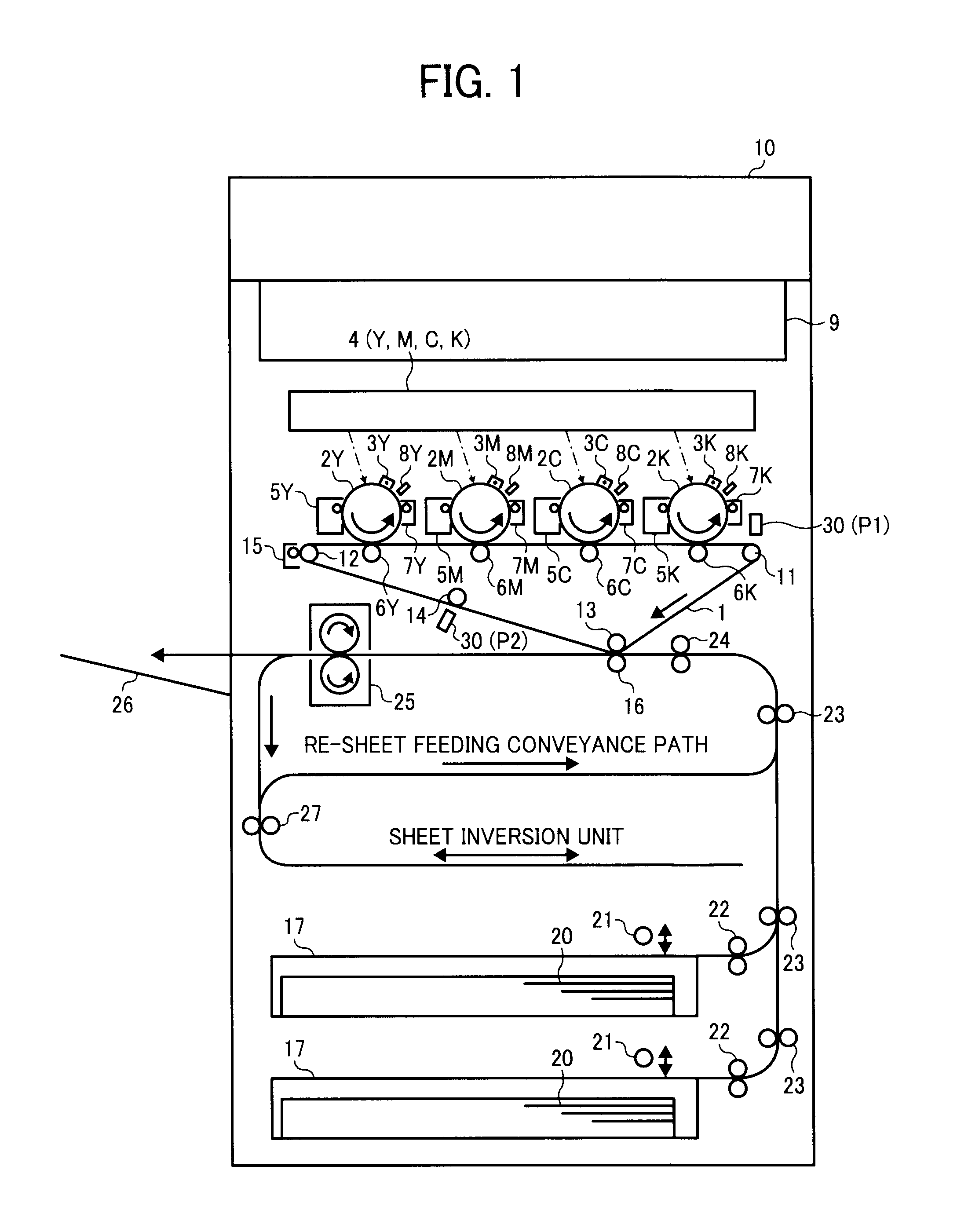
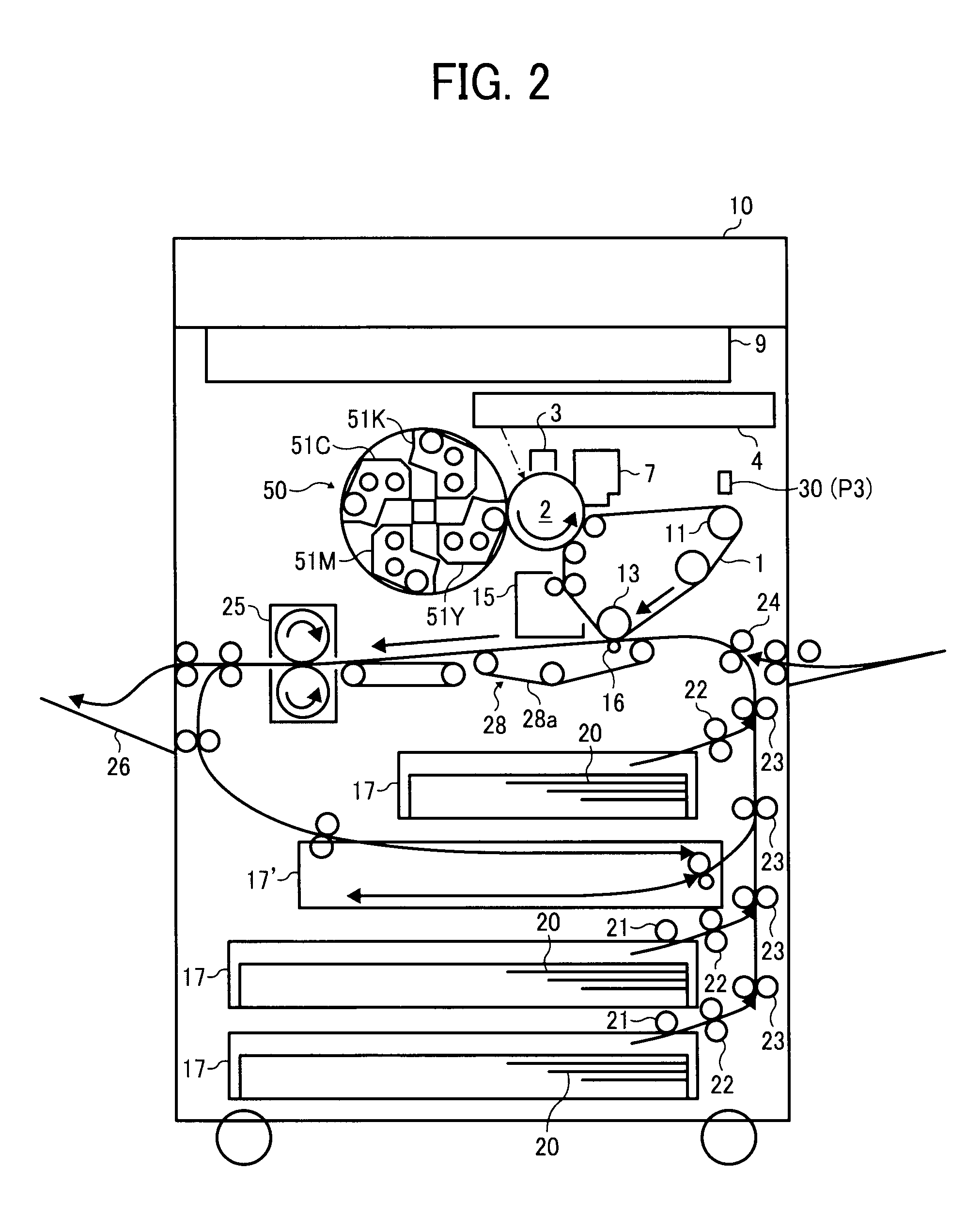
[0051]Referring now to the drawings, wherein like reference numerals designate identical or corresponding parts throughout the several views thereof and in particular to FIG. 1, a configuration of an image forming apparatus, to which the present invention is applicable, is described. Although, FIG. 1 illustrates a full-color machine that employs a four-consecutive tandem type intermediate transfer system as an image forming apparatus of an electronic photographic system, to which the present invention is applicable, the present invention can be applied another imaging forming apparatus, such as a full-color machine employing a four tandem type direct transfer system, a full-color machine employing one-drum type intermediate transfer system, etc., as described later in detail. Further, the present invention can be applied to a monochrome machine, such as a machine employing a one-drum type direct transfer system, etc.

[0052]As shown in FIG. 1, multiple photoconductive drums 2Y, 2M, 2C...


PUM


Abstract

In an image forming apparatus, a first controller forms a first image pattern on an image bearer and determines a first image formation condition based on a detection result of density of a toner image. The first controller then controls a toner image forming device based on the first image formation condition. A second controller forms a second image pattern different from the first image pattern on an image bearer and determines a second image formation condition based on a detection result of density of a toner image. The second controller then controls a toner image forming device based on the second image formation condition.

Description

CROSS-REFERENCE TO RELATED APPLICATION[0001]This patent application is based on and claims priority pursuant to 35 U.S.C. §119 to Japanese Patent Application Nos. 2011-022284 and 2011-076200, filed on Feb. 4 and Mar. 30, 2011, respectively, in the Japanese Patent Office, the entire disclosures of which are hereby incorporated by reference herein.BACKGROUND OF THE INVENTION[0002]1. Field of the Invention[0003]This invention relates to an image forming apparatus, such as a copier, a printer, a facsimile machine, a printer, etc.[0004]2. Description of the Related Art[0005]Conventionally, image forming apparatuses are known that reduce density irregularity of a toner image formed on an image bearer.[0006]For example, Japanese Patent Publication No. 62-145266 (JP-S62-145266-A) discloses a technology in which an image recorder (i.e., an image forming apparatus) scans a modulated laser beam onto a photoconductive drum (i.e., an image bearer) to record a latent image thereon and then applie...

Claims


Application Information

Patent Timeline
Patent Type & Authority Applications(United States)
IPC IPC(8): G03G15/00
CPCG03G15/5058G03G2215/0141G03G2215/0129G03G2215/0116
Inventor HIRAI, SHUJIKANEKO, SATOSHIKATO, SHINJIYAMANE, JUNKUDO, KOICHISUZUKI, SHINGO
Owner RICOH KK
Why Eureka
Try Eureka