Method and device for long-duration navigation

a long-term navigation and vehicle technology, applied in the direction of navigation instruments, surveying and navigation, instruments, etc., can solve the problems of affecting the accuracy of gyros, affecting the degradation of navigation performance, and navigation errors, and achieve the effect of less expensiv

Active Publication Date: 2012-08-09
SAFRAN ELECTRONICS & DEFENSE
View PDF1 Cites 6 Cited by
  • Summary
  • Abstract
  • Description
  • Claims
  • Application Information

AI Technical Summary

Benefits of technology

[0030]This makes it possible to implement rotations of the inertial unit with a mechanical turnover device having only three motor-driven shafts, without running the risk of two of the motor-driven shafts lying on axes that come into coincidence. Such a mechanical turnover device is much less expensive and bulky than a mechanical device having four motor-driven shafts as would otherwise be necessary in the absence of two configurations.

Problems solved by technology

The accuracy of the gyros is affected by drift errors (shifting of the measurement origin, such that a magnitude of zero is not always measured as being zero), by scale factors (a scale factor error is an error concerning the coefficients by which the measurement is multiplied), and by axis setting errors (orthogonality error between the measurement axes).
Unfortunately, such measurements include noise that, on being integrated, gives rise to navigation errors such as random walks.
Those errors have an influence on the degradation of navigation performance.
In addition, the measurements provided by the gyros incorporate a component associated with rotation of the Earth and thus affected by the scale factor errors specific to each gyro.
Furthermore, the method described in that document can be used only with sensors having drift error that remains constant over the entire measurement range.
That method is therefore not suitable for use with vibratory gyros that are conventionally used in inertial systems used for navigation, e.g. as happens in a gyro-compass adapted to provide an angle measurement relative to a reference direction (or heading) such as geographical north.
The measurements provided by such vibratory gyros may suffer from errors that are essentially a function of the position of the vibration relative to the measurement electrode.

Method used


Image

  • Method and device for long-duration navigation
  • Method and device for long-duration navigation
  • Method and device for long-duration navigation

Examples


Embodiment Construction

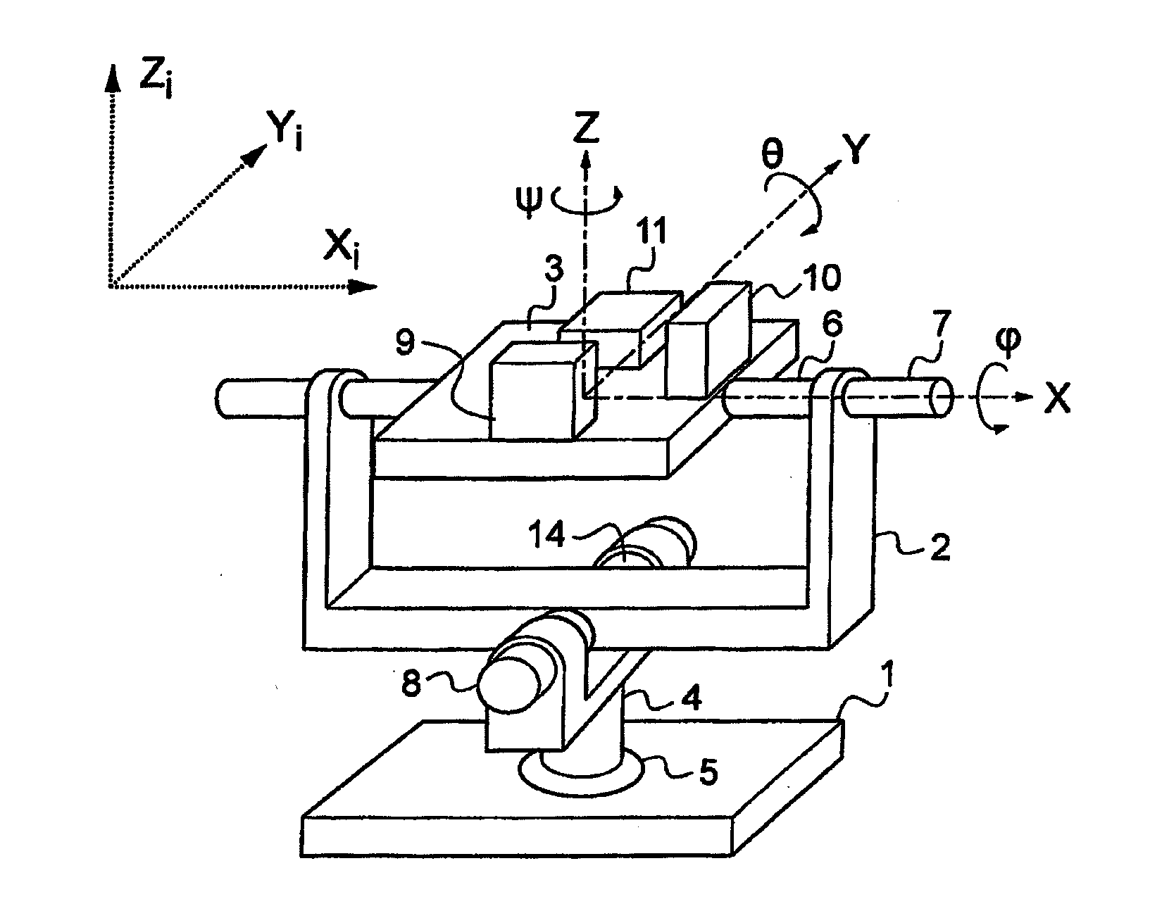
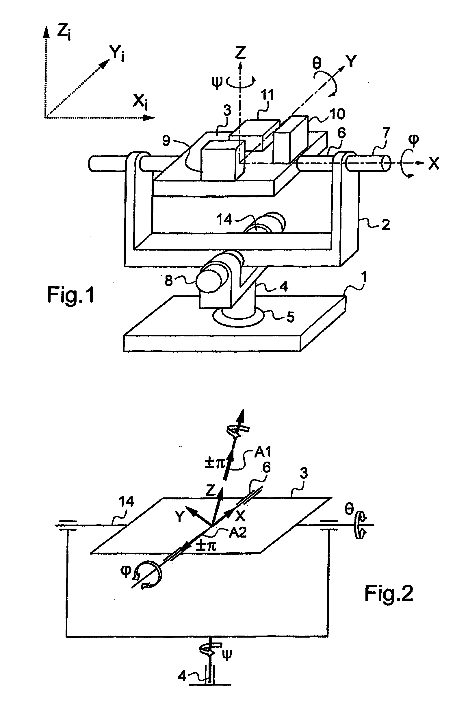
[0040]With reference to FIG. 1, a platform 1 is secured to a vehicle, such as a ship, for example. The platform 1 supports a gimbal 2 for keeping three axes X, Y, Z of an axis system associated with an inertial unit 3 along three axes Xi, Yi, Zi of a stationary inertial axis system of arbitrary origin, e.g. the center of the Earth in this example. The axes Xi and Yi lie in an equatorial plane, and the axis Zi points vertically upwards. A first degree of freedom in rotation is given by a shaft 4 that is secured to the vehicle. A motor 5 enables the shaft 4 to be turned so as to eliminate the effects of changes in the heading of the carrier. A second degree of freedom in rotation is given by a shaft 6, secured to the inertial unit 3. A motor 7 enables the shaft 6 to be turned so as to cancel the effects of the carrier turning about the axis of the shaft 6. A third degree of freedom in rotation is given by a third shaft 14 perpendicular to the shafts 4 and 6. A motor 8 enables the thir...


PUM


Abstract

A long-term navigation method using an inertial unit associated with a system of axes X, Y, Z and mounted on a vehicle traveling relative to the Earth in order to measure its movements relative to an inertial frame of reference having axes Xi, Yi, and Zi. The method includes the steps of acting in permanent manner to measure an orientation of the system of axes X, Y, Z in the inertial frame of reference and applying a predetermined sequence of turnovers to the inertial unit in the inertial frame of reference about first and second axes that are substantially perpendicular to each other and in such a manner that at the end of the sequence the inertial unit is in a final orientation identical to its initial orientation relative to the inertial frame of reference, with the turnovers canceling within the sequence.

Description

FIELD OF THE INVENTION[0001]The present invention relates to a method for long-term navigation of a vehicle by means of an inertial navigation unit associated with the vehicle. The vehicle may be a terrestrial vehicle, an aircraft, or a ship, with navigation thereof requiring knowledge of its position, its speed, and its attitude (heading, roll, and pitch). The invention also relates to a navigation device for implementing the method.BACKGROUND OF THE INVENTION[0002]A modern inertial navigation unit generally comprises inertial sensors such as gyros and accelerometers arranged on axes of a measurement axis system associated with a support platform for the inertial unit. The gyros measure angular rotations of the measurement axis system relative to a geographical frame of reference and they supply the attitude of the vehicle in the geographical frame of reference. The accelerometers measure accelerations that are projected onto the geographical frame of reference and then integrated ...

Claims


Application Information

Patent Timeline
Patent Type & Authority Applications(United States)
IPC IPC(8): G01C21/18
CPCG01C21/16G01C21/166G01C21/183
Inventor LIGNON, CHRISTIAN
Owner SAFRAN ELECTRONICS & DEFENSE
Why Eureka
Try Eureka