Positioning tube of a vegetation cutter

a technology of positioning tube and vegetation cutter, which is applied in the direction of metal working apparatus, agriculture tools and machines, agriculture, etc., can solve the problems of inconvenient assembly of multiple supporting ribs in protective tubes, and the inability to quickly and easily assembly precisely machined positioning tubes, etc., to achieve convenient positioning, simple structure, and light weight

Inactive Publication Date: 2012-08-16
YAO I FABRIC
View PDF11 Cites 2 Cited by
  • Summary
  • Abstract
  • Description
  • Claims
  • Application Information

AI Technical Summary

Benefits of technology

[0007]The present invention relates to a vegetation cutter and comprises a tubular casing with a power source and a cutting member connected to two ends thereof. A drive cable extends through the casing and is connected to the power source. The cutting member is connected to and driven by the drive cable. A positioning tube is axially located in the casing and has an annular sleeve through which the drive ...

Problems solved by technology

Nevertheless, the multiple supporting ribs are not convenient for assembling in the pr...

Method used


Image

  • Positioning tube of a vegetation cutter
  • Positioning tube of a vegetation cutter
  • Positioning tube of a vegetation cutter

Examples


Embodiment Construction

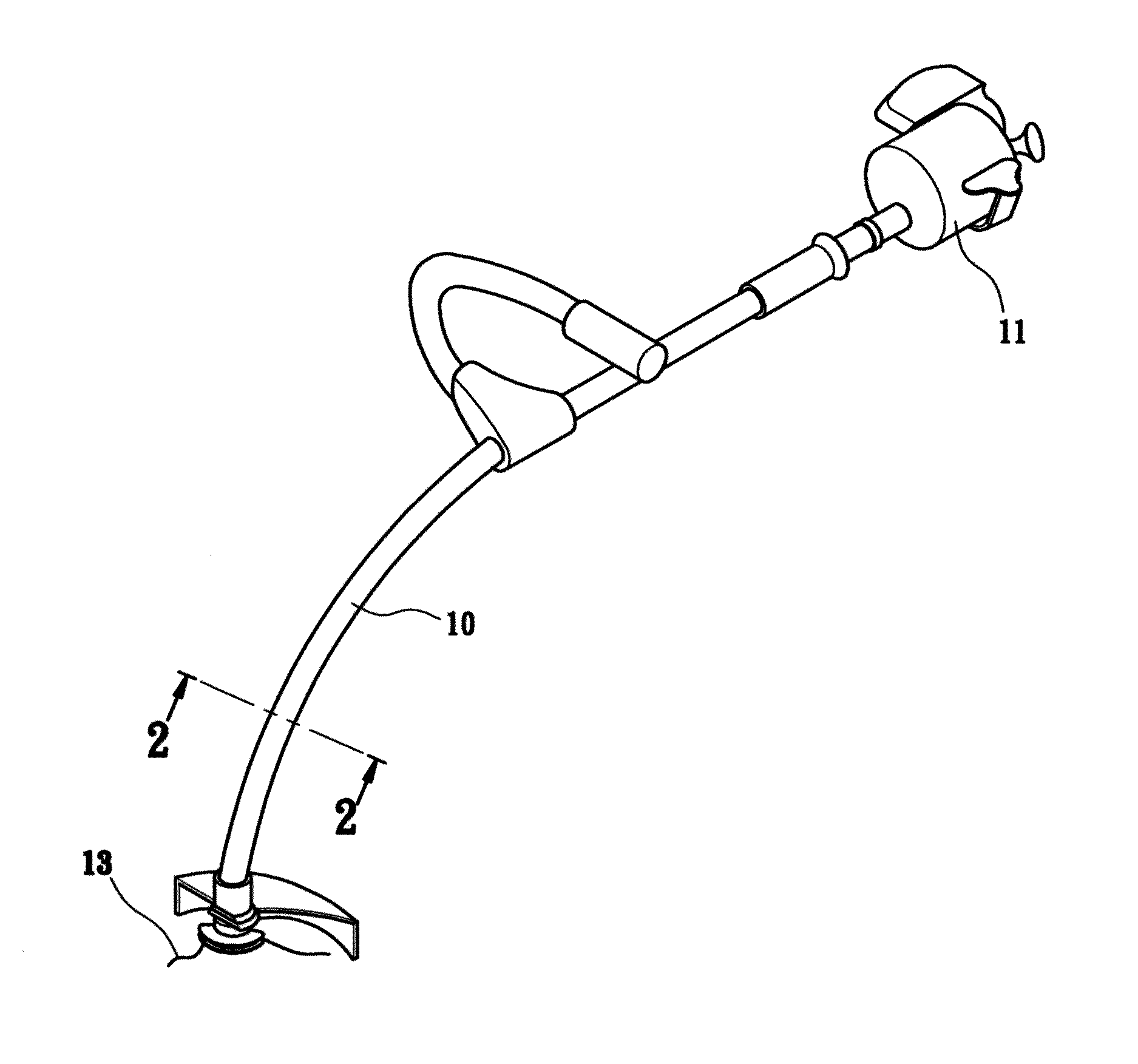
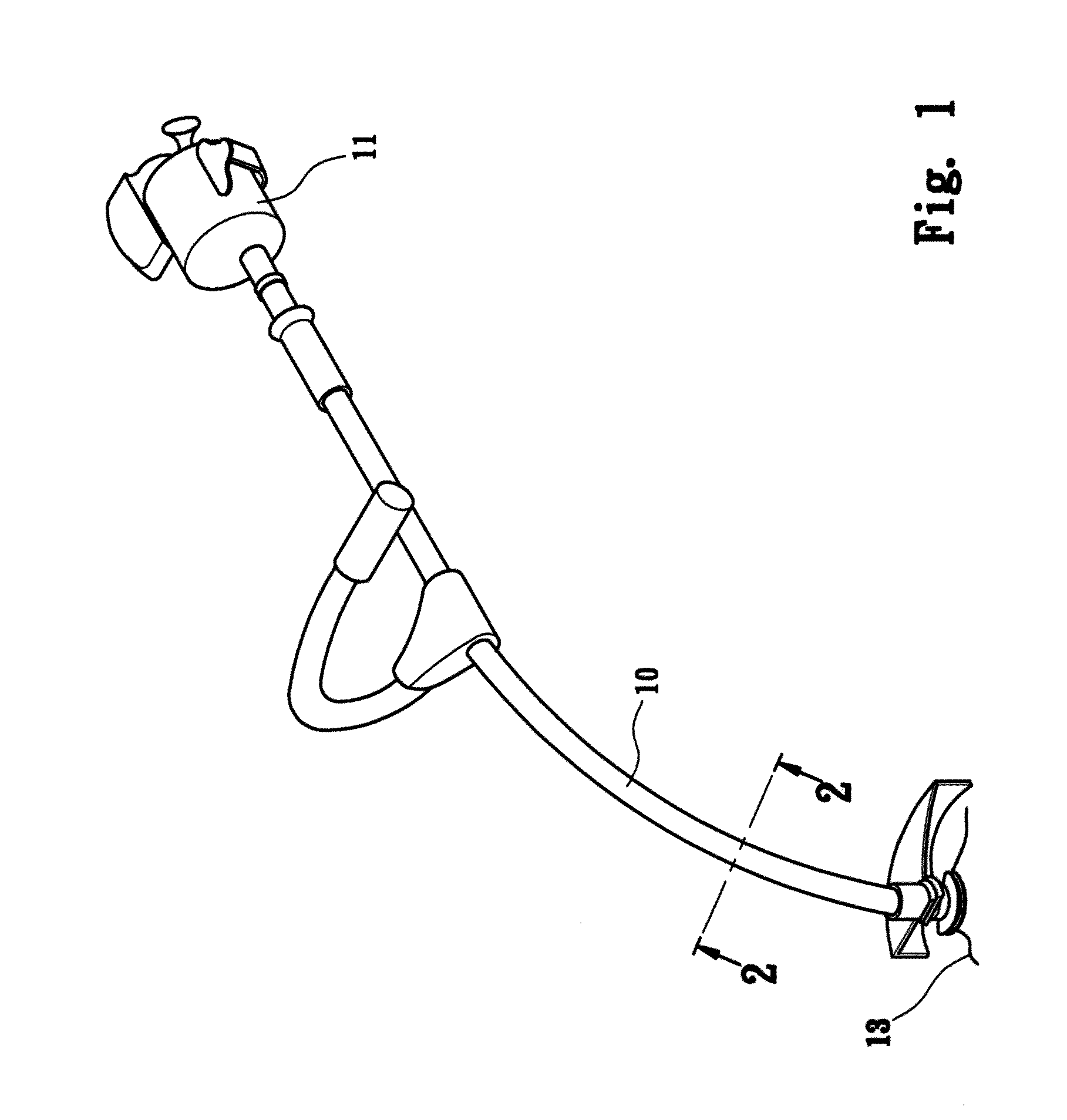
[0015]Referring to FIGS. 1 to 3, the vegetation cutter generally comprises a tubular casing 10, power source 11 connected to the first end of the casing 10, a cutting member 13 connected to the second end of the casing 10, and a positioning tube of the present invention received in the casing 10.

[0016]The power source 11 is a motor or an engine, and a drive cable 12 is connected to the power source 11 and driven by the power source 11. The drive cable 12 extends through the casing 10 and is made of metal and includes proper flexible and preset torque.

[0017]The cutting member 13 is connected to the drive cable 12 and rotated by the drive cable 12. The cutting member 13 is a blade or a cutting line.

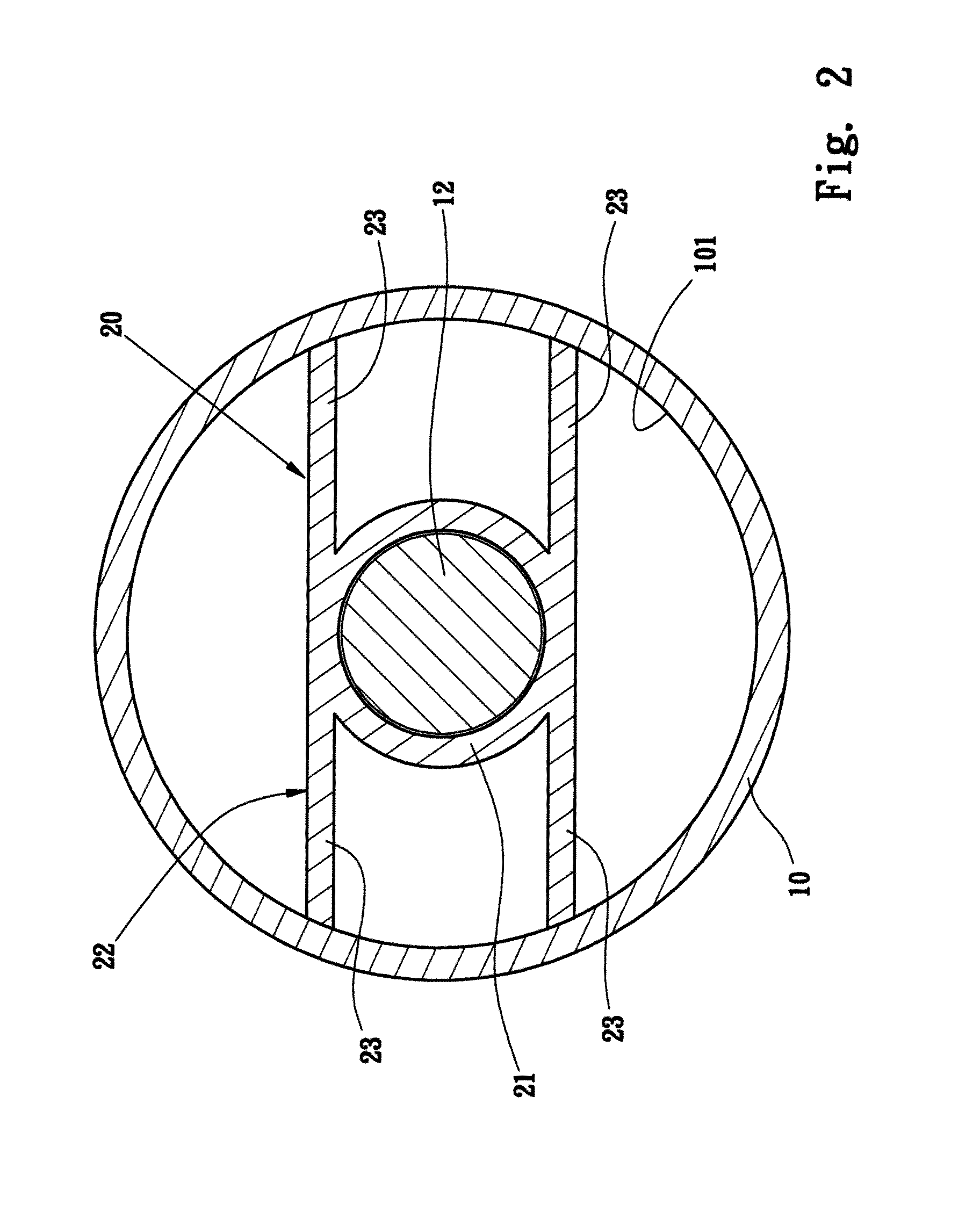
[0018]The positioning tube 20 is axially located in the casing 10 and has an annular sleeve 21 through which the drive cable 12 rotatably extends. The sleeve 21 has two rib portions 22 tangentially connected thereto and the two rib portions 22 are parallel to each other. Each rib portion 22...


PUM


Abstract

A vegetation cutter includes a tubular casing and a power source is connected to a first end of the casing so as to drive a drive cable which extends through the casing. A cutting member is connected to the drive cable and located on a second end of the casing. A positioning tube is axially located in the casing and has an annular sleeve through which the drive cable extends. The sleeve has two rib portions tangentially connected thereto and the two rib portions are parallel to each other. Each rib portion has two ribs on two ends thereof and the two ribs contact an inner periphery of the casing. The ribs are flexible and position the positioning tube in the casing, and absorb vibration when in use.

Description

FIELD OF THE INVENTION[0001]The present invention relates to a positioning tube for a vegetation cutter, and more particularly, to a positioning tube with ribs which, are flexible and in contact to inside of the positioning tube.BACKGROUND OF THE INVENTION[0002]A conventional vegetation cutter generally includes a tubular casing with a power source and a cutting member connected to two ends of the casing. A flexible drive cable extends through the casing and is driven by the power source so as to rotate the cutting member which cuts the plants. The cutting member can be a blade or a cutting line.[0003]A positioning tube is located in the casing and located between the drive cable and the casing. Multiple ribs extend from the positioning tube. When the power source is activated, the drive cable generates vibration which can be absorbed by the positioning tube and reduces friction between the drive cable and the casing.[0004]A conventional positioning tube is disclosed in U.S. Pat. No...

Claims


Application Information

Patent Timeline
IPC IPC(8): A01D34/416
CPCA01D34/905
Inventor YANG, TSUNG PEI
Owner YAO I FABRIC
Why Eureka
Try Eureka