Low cost parabolic solar concentrator and method to develop the same

a parabolic solar concentrator and low cost technology, applied in the direction of mirrors, solar thermal energy generation, roll mill control devices, etc., can solve the problems of high cost, inability to meet the requirements of the project, so as to achieve easy and low cost , the effect of low cos

Active Publication Date: 2012-08-16
TOYOTA MOTOR CO LTD
View PDF2 Cites 2 Cited by
  • Summary
  • Abstract
  • Description
  • Claims
  • Application Information

AI Technical Summary

Benefits of technology

[0007]The present invention relates to a low cost parabolic solar concentrator and method to develop the same. The parabolic solar concentrator can be formed by deforming a hybrid plate. Force can be applied to an edge portion of the hybrid plate and / or a middle portion of the hybrid plate. Alternatively, the edge portion and / or the middle portion can be held in place while force is applied to the portion that is not held in place. When force is applied in such a manner to the hybrid plate, the hybrid plate is deformed into a parabolic solar concentrator, instead of a sinusoidal shape. Thus, the use of the hybrid plate allows for an easy and low cost formation of the parabolic solar concentrator.
[0011]Thus, the characteristics of the first plate, the second plate, and the third plate, can be chosen to allow the hybrid plate to be deformed into the parabolic shape with the application of forces on the edge portion of the hybrid plate and / or the middle portion of the hybrid plate. This can reduce a cost of producing a parabolic solar concentrator.

Problems solved by technology

However, producing the conventional parabolic solar concentrator from the single plate is difficult and expensive.
When force is applied to an edge portion of the single plate and / or a middle portion of the single plate, the single plate would be in a sinusoidal shape, and prone to being over bent or under bent.
However, this method is generally expensive and inaccurate since it is difficult to repetitively apply the incremental force and repetitively smooth out the single plate in order to form the conventional parabolic solar concentrator.
However, each parabolic mold is generally expensive to produce.
While this may be acceptable for a conventional parabolic solar concentrator with only a single size and shape, it is unacceptable if the conventional parabolic solar concentrators are in multiple sizes and shapes.
This is because each size or shape of the conventional parabolic solar concentrators would require a different mold, which can rapidly increase expenses.
Therefore, this approach is also undesirable.

Method used


Image

  • Low cost parabolic solar concentrator and method to develop the same
  • Low cost parabolic solar concentrator and method to develop the same
  • Low cost parabolic solar concentrator and method to develop the same

Examples


Embodiment Construction

[0025]Apparatus, systems and methods that implement the embodiments of the various features of the present invention will now be described with reference to the drawings. The drawings and the associated descriptions are provided to illustrate some embodiments of the present invention and not to limit the scope of the present invention. Throughout the drawings, reference numbers are re-used to indicate correspondence between referenced elements.

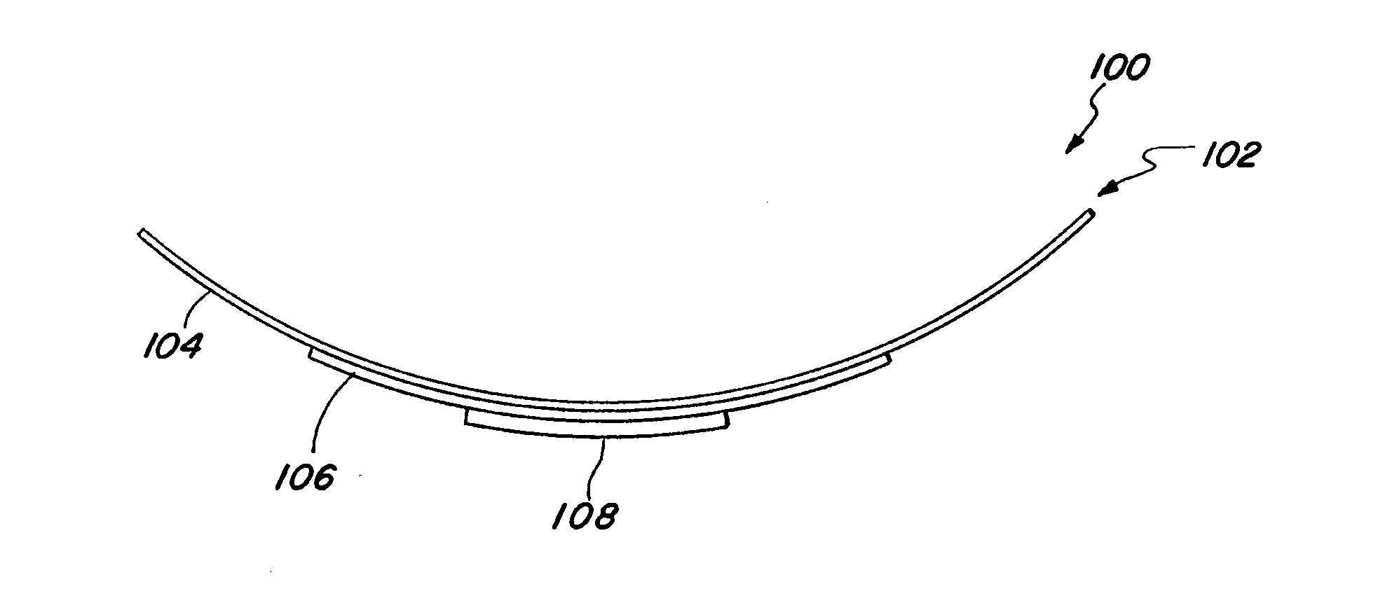
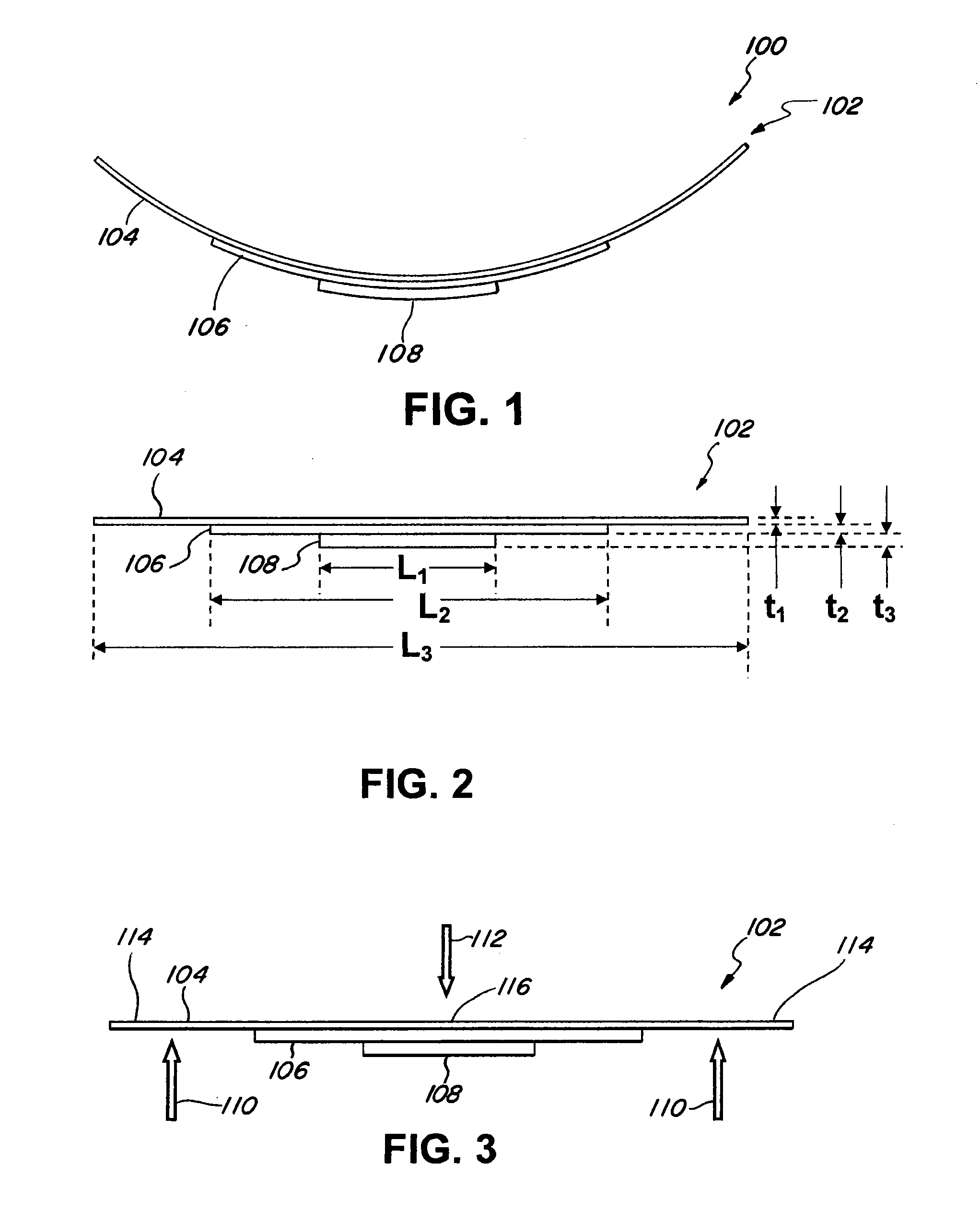
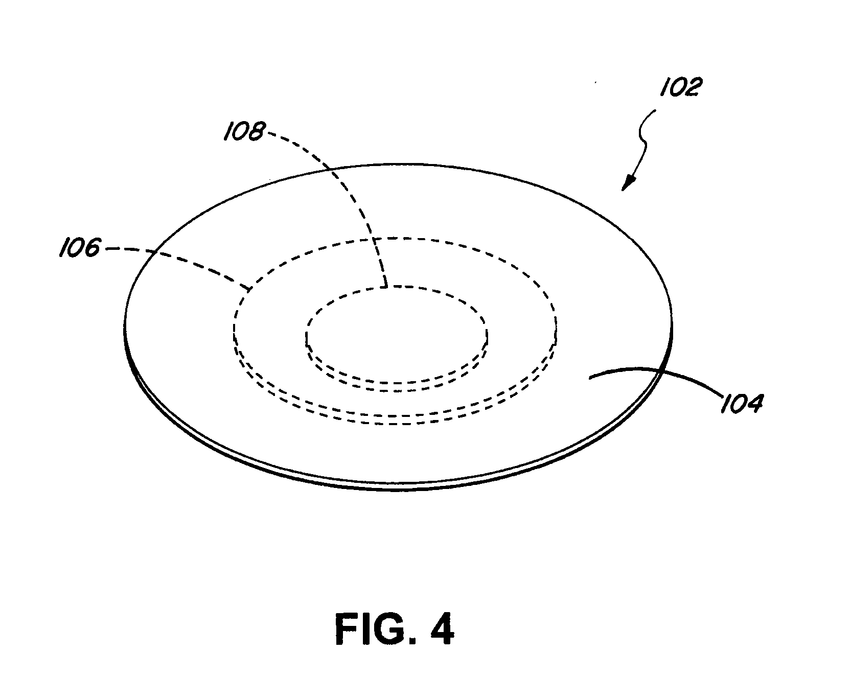
[0026]In one embodiment, the present invention includes, for example, a parabolic solar concentrator 100 as shown in FIG. 1. The parabolic solar concentrator 100 can be formed, for example, from a hybrid plate 102 that is deformed into a parabolic shape. The hybrid plate 102 can include, for example, a first plate 104, a second plate 106, and / or a third plate 108. The parabolic solar concentrator 100 can be formed from the hybrid plate 102 by deforming the hybrid plate 102 into a parabolic shape through the application of forces on an edge por...


PUM

PropertyMeasurementUnit
lengthaaaaaaaaaa
forceaaaaaaaaaa
thicknessaaaaaaaaaa

Abstract

The present invention relates to a low cost parabolic solar concentrator and method to develop the same. The parabolic solar concentrator can be formed by deforming a hybrid plate. Force can be placed on an edge portion of the hybrid plate and / or a middle portion of the hybrid plate. The selective application of the force deforms the hybrid plate into a parabolic solar concentrator, instead of a sinusoidal shape. The hybrid plate can be formed from a first plate, a second plate, and a third plate attached to each other. The characteristics of the first plate, the second plate, and the third plate, can be chosen to allow the hybrid plate to be deformed into the parabolic shape with the selective application of forces.

Description

BACKGROUND[0001]1. Field[0002]The present invention relates to a low cost parabolic solar concentrator and method to develop the same.[0003]2. Description of the Related Art[0004]To produce a conventional parabolic solar concentrator, a single plate is normally used. However, producing the conventional parabolic solar concentrator from the single plate is difficult and expensive. When force is applied to an edge portion of the single plate and / or a middle portion of the single plate, the single plate would be in a sinusoidal shape, and prone to being over bent or under bent. The single plate would not be in a parabolic shape. Thus, incremental force has to be applied to the single plate to ensure that the single plate is in the parabolic shape. In addition, the single plate has to be smoothed out to ensure that there are no lumps from the incremental force so that the single plate can be used to concentrate light. However, this method is generally expensive and inaccurate since it i...

Claims


Application Information

Patent Timeline
Patent Type & Authority Applications(United States)
IPC IPC(8): F24J2/12B21D31/00F24S23/71F24S23/70
CPCB21D11/10H01L31/0547B21B37/00B29D11/00596B32B9/00B32B15/04C07B61/00C21D9/46F24J2/1057F24J2/12G02B5/10G06F17/50F24J2002/4678G02B27/0012Y02E10/42B32B7/045B32B15/06B32B1/00B32B2250/03B32B2307/40B32B2551/00F21V7/06F21V7/10Y02E10/52B21D51/08B21D35/007B32B7/05F24S23/71F24S23/82F24S2025/6011Y02E10/40
Inventor GANDHI, UMESH N.
Owner TOYOTA MOTOR CO LTD
Why Eureka
Try Eureka