
Light-Emitting Module, Light-Emitting Panel, and Lighting Device

Active Publication Date: 2012-08-16
SEMICON ENERGY LAB CO LTD
View PDF6 Cites 25 Cited by
  • Summary
  • Abstract
  • Description
  • Claims
  • Application Information

AI Technical Summary

Benefits of technology

[0011]Another object of one embodiment of the present invention is to provide a lighting device in which a light-emitting element suffering a short-circuit failure does not cause wasteful electric power consumption. Another object of one embodiment of the present invention is to provide a lighting device in which a light-emitting element suffering a short-circuit failure does not allow the reliability to lower.
[0027]In accordance with one embodiment of the present invention, it is possible to provide any of the following: a light-emitting module in which a light-emitting element suffering a short-circuit failure does not cause wasteful electric power consumption; a light-emitting panel in which a light-emitting element suffering a short-circuit failure does not allow the reliability of an adjacent light-emitting element to lower; a lighting device in which a light-emitting element suffering a short-circuit failure does not cause wasteful electric power consumption; and a light-emitting module in which a light-emitting element causing a short-circuit failure does not allow the reliability to lower.

Problems solved by technology

Incidentally, there has been a problem in that a short-circuit failure could easily be caused by entry of an extraneous substance between a pair of electrodes because the thickness of an EL layer is as thin as several tens of nanometers to several hundreds of nanometers.
A short circuit between the pair of electrodes of an organic EL element causes the organic EL element not only to cease lighting but also to generate heat, which results in wasteful electric power consumption.
Further, when another organic EL element is provided to be adjacent to the short-circuiting organic EL element, the adjacent organic EL element might break down or deteriorate due to the heat generated by the short-circuiting organic EL element.
Further, a short circuit in an organic EL element connected to a constant-voltage power source in particular might not only cease lighting of the organic EL element but also cause a fire.

Method used


Image

  • Light-Emitting Module, Light-Emitting Panel, and Lighting Device
  • Light-Emitting Module, Light-Emitting Panel, and Lighting Device
  • Light-Emitting Module, Light-Emitting Panel, and Lighting Device

Examples


embodiment 1

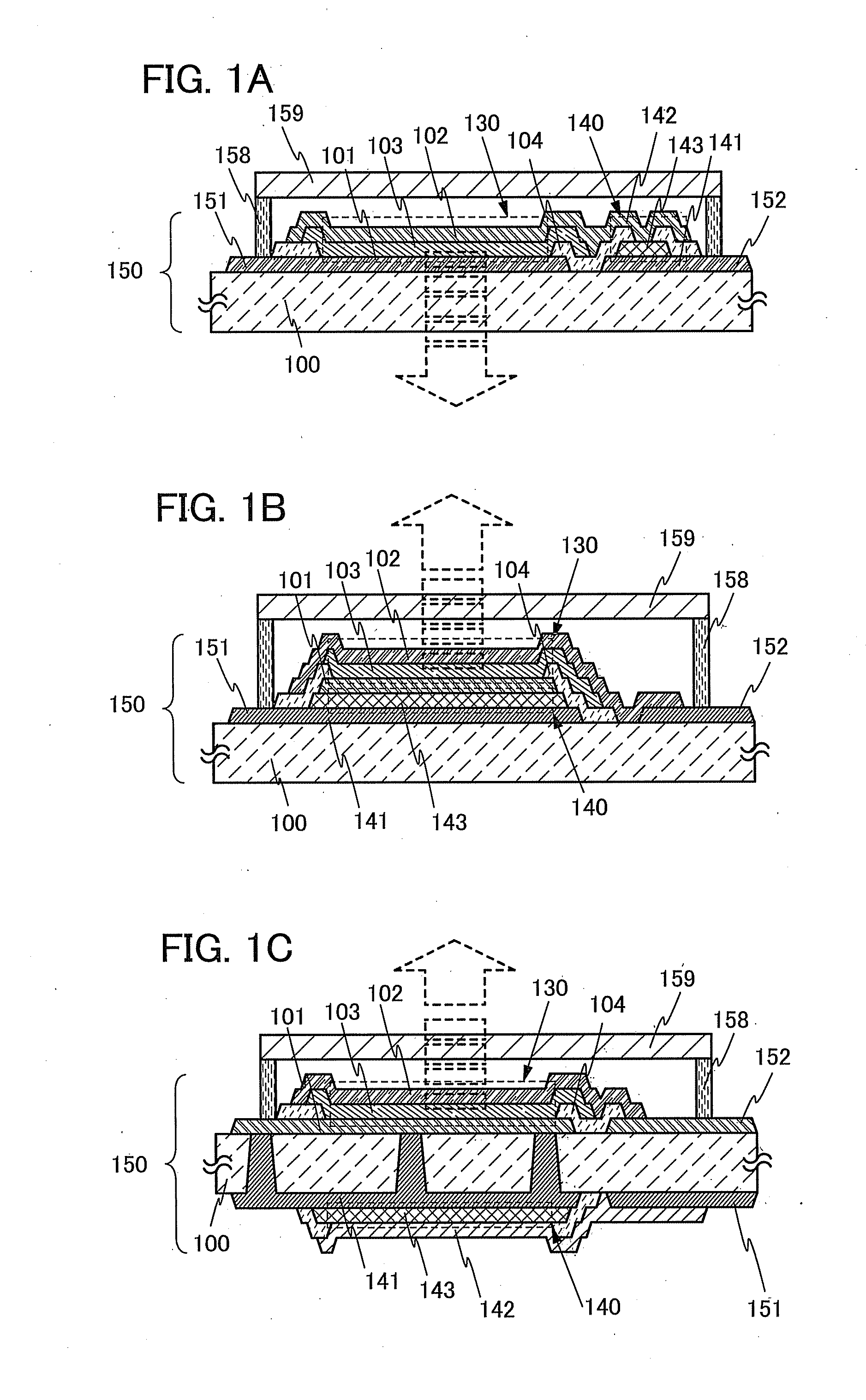
[0039]With reference to FIGS. 1A to 1C, this embodiment illustrates a light-emitting module having a structure in which electric power is supplied to a light-emitting element through a positive temperature coefficient thermistor thermally coupled with the light-emitting element, and specifically illustrates a light-emitting module including an organic EL element over a substrate and a positive temperature coefficient thermistor thermally coupled with the organic EL element, in which electric power is supplied to the organic EL element through the positive temperature coefficient thermistor.

[0040]A structure of a light-emitting module 150 in accordance with one embodiment of the present invention is illustrated in FIG. 1A. The light-emitting module 150 exemplified in FIG. 1A includes a light-emitting element 130 and a positive temperature coefficient thermistor 140 over a substrate 100. In addition, the light-emitting element 130 is separated from impurities in the air by a sealant 1...

modification example 1

[0054]Another mode of a light-emitting module in accordance with one embodiment of the present invention is illustrated in FIG. 1B. The light-emitting module 150 exemplified in FIG. 1B includes the positive temperature coefficient thermistor 140 over the substrate 100 and the light-emitting element 130 over the positive temperature coefficient thermistor 140. In addition, the light-emitting element 130 is separated from impurities in the air by the sealant 158 which surrounds the light-emitting element 130 and the sealing material 159 which can transmit light emitted by the light-emitting element 130.

[0055]The positive temperature coefficient thermistor 140 is included between the substrate 100 and the light-emitting element 130. The positive temperature coefficient thermistor 140 includes the PTC layer 143 having a positive temperature coefficient between the lower electrode 141 and the first electrode 101 of the light-emitting element.

[0056]The positive temperature coefficient the...

modification example 2

[0061]Another mode of a light-emitting module in accordance with one embodiment of the present invention is illustrated in FIG. 1C. In the light-emitting module 150 exemplified in FIG. 1C, the light-emitting element 130 on one side of the substrate 100 and the positive temperature coefficient thermistor 140 on the opposite side of the substrate 100 are included so as to overlap with each other. In addition, the light-emitting element 130 is separated from impurities in the air by the sealant 158 which surrounds the light-emitting element 130 and the sealing material 159 which can transmit light emitted by the light-emitting element 130.

[0062]The sides of the substrate 100 each have an insulating surface, one of which is provided with the first electrode 101 of the light-emitting element 130 and the opposite of which is provided with the lower electrode 141 of the positive temperature coefficient thermistor 140. The light-emitting element 130 includes the first electrode 101 in conta...


PUM


Abstract

An object is to provide a light-emitting module in which a light-emitting element suffering a short-circuit failure does not cause wasteful electric power consumption. Another object is to provide a light-emitting panel in which a light-emitting element suffering a short-circuit failure does not allow the reliability of an adjacent light-emitting element to lower. Focusing on heat generated by a light-emitting element suffering a short-circuit failure, provided is a structure in which electric power is supplied to a light-emitting element through a positive temperature coefficient thermistor (PTC thermistor) thermally coupled with the light-emitting element.

Description

BACKGROUND OF THE INVENTION[0001]1. Field of the Invention[0002]The present invention relates to a light-emitting module, a light-emitting panel including a plurality of light-emitting modules, and a lighting device using the light-emitting module. In particular, the invention relates to a light-emitting module including a light-emitting element with a planar light-emitting region, a light-emitting panel including a plurality of the light-emitting modules, and a lighting device using the light-emitting module.[0003]2. Description of the Related Art[0004]Light-emitting elements, in which a layer that includes a light-emitting organic compound and spreads as a film (also referred to as EL layer) is provided between a pair of electrodes, have been known. Such light-emitting elements are called organic EL elements, for example, and light emission can be obtained from the light-emitting organic compound upon application of a voltage between the pair of electrodes. In addition, examples o...

Claims


Application Information

Patent Timeline
IPC IPC(8): H01L33/36H01L27/15
CPCH01L2251/5361H01L27/3204H01L51/5278H01L27/3202H01L2251/5392H01L27/3225H10K59/84H10K59/86H10K50/19H10K2102/341H10K59/805H10K59/8722H01L33/647H01L33/645H01L33/64H10K59/00H10K50/11H10K50/81H10K50/82H10K50/87H10K2102/361
Inventor HIROKI, MASAAKISEO, SATOSHINAKAMURA, YASUO
Owner SEMICON ENERGY LAB CO LTD
Features
  • Generate Ideas
  • Intellectual Property
  • Life Sciences
  • Materials
  • Tech Scout
  • Unparalleled Data Quality
  • Higher Quality Content
  • 60% Fewer Hallucinations
Learn More