Bench-top measurement method, apparatus and system for phased array radar apparatus calibration

a phased array and radar technology, applied in the field of radar equipment, can solve problems such as difficulties in integration

Inactive Publication Date: 2012-08-16
SRC INC
View PDF52 Cites 19 Cited by
  • Summary
  • Abstract
  • Description
  • Claims
  • Application Information

AI Technical Summary

Benefits of technology

[0010]Embodiments of the invention include: (1) a method for determining values of performance parameters for a plurality of operational phased array radar antenna subarrays; and (2) a method for calibrating a phased array radar apparatus that may use the plurality of operati

Problems solved by technology

It is anticipated that such integration may present difficulties since determination of values of performance parameters of a combining network component may not nec

Method used


Image

  • Bench-top measurement method, apparatus and system for phased array radar apparatus calibration
  • Bench-top measurement method, apparatus and system for phased array radar apparatus calibration
  • Bench-top measurement method, apparatus and system for phased array radar apparatus calibration

Examples


Embodiment Construction

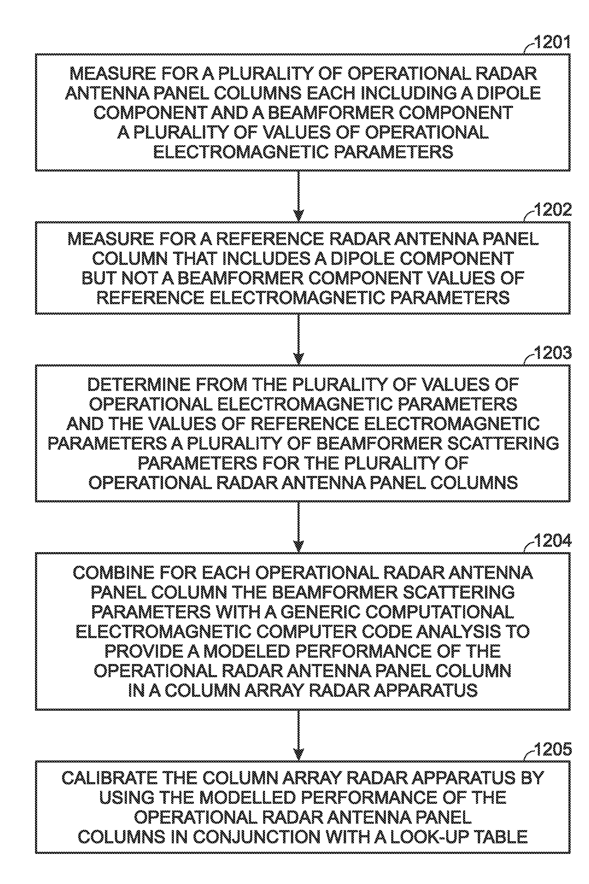
[0026]The embodiments, which include in-part: (1) a method for determining values for performance parameters for a plurality of operational phased array radar antenna subarrays; as well as (2) a method for calibrating a column array radar apparatus that may use the plurality of operational phased array radar antenna subarrays, are understood within the context of an illustrative non-limiting embodiment, a description of which is set forth below. The description set forth below is understood within the context of the drawings described above. Since the drawings are intended for illustrative purposes, the drawings are not necessarily drawn to scale.

[0027]Within the context of this illustrative non-limiting embodiment described in greater detail below, the embodiments and the invention derive from a particular observation with respect to performance and calibration of a phased array radar apparatus (i.e., which will be described within the context of a specific illustrative non-limitin...


PUM


Abstract

A method for determining beamformer scattering parameters for a plurality of phased array radar antenna subarrays that each include a radiating (e.g., dipole) component and a beamformer component provides for obtaining for the plurality of phased array radar antenna subarrays a plurality of electromagnetic measurements at a plurality of ports. Analogous electromagnetic measurements are obtained for a reference subarray including a radiating component but absent a beamformer component. The plurality of phased array radar antenna subarray electromagnetic measurements and the reference subarray electromagnetic measurements provide a plurality of beamformer scattering parameter values for the plurality of phased array radar antenna subarrays that may be used in modeling and calibrating a phased array radar apparatus that may be assembled from the plurality of phased array radar antenna subarrays.

Description

STATEMENT OF GOVERNMENT INTEREST[0001]This work derives from research under Government Contract W15P7T-05-C-P004. The U.S. Government has rights in this invention.BACKGROUND OF THE INVENTION[0002]1. Field of the Invention[0003]The invention relates generally to radar apparatus. More particularly, the invention relates to efficient calibration of radar apparatus that may provide for, but is not necessarily limited to, accurate angle-of-arrival calibration of a phased array radar apparatus.[0004]2. Description of the Related Art[0005]Radar apparatus are commonly used in commercial and military settings for purposes of identifying and tracking a particular radar target within a particular geometric radar field of interest. In order to provide for accurate identification and tracking of such a radar target, radar apparatus typically require calibration. For example, accurate angle-of-arrival measurement within a radar apparatus often requires calibration of a radar antenna within the ra...

Claims


Application Information

Patent Timeline
IPC IPC(8): G01S7/40
CPCG01S7/4026G01S2013/0245H01Q3/242G01S2007/403H01Q3/267H01Q21/205G01S2007/4034H01Q3/2605G01S7/4034G01S7/403
Inventor SCHUMAN, HARVEY K.DAVIS, ANTHONY M.MCPHERSON, DONALD M.ROBINSON, MICHAELHAGENMAYER, DAVID R.WILEY, JOHN G.
Owner SRC INC
Why Eureka
Try Eureka