Three-dimensional correlated imaging method based on phased array radar

A phased array radar and associated imaging technology, which is applied in the directions of radio wave reflection/re-radiation, utilization of re-radiation, measurement devices, etc., can solve the problems of high signal processing difficulty, low resolution, limited application occasions, etc.

Active Publication Date: 2014-12-03
XIDIAN UNIV
View PDF5 Cites 20 Cited by
  • Summary
  • Abstract
  • Description
  • Claims
  • Application Information

AI Technical Summary

Problems solved by technology

The former uses single-antenna or linear array scanning to form a two-dimensional synthetic aperture to obtain two-dimensional resolution capabilities across the distance plane, and then combines range-to-pulse compression technology to obtain a full three-dimensional target distribution image. This type of method requires platform movement and has limited applications. , the real-time data acquisition is poor, and the signal processing is difficult; while the latter relies on the narrow beam formed by the array antenna to scan in space to obtain a three-dimensional image, and its resolution depends on the beam width, that is, the real physical aperture size of the antenna. Obtaining high-resolution images requires increasing the aperture of the array, which increases the complexity and cost of the system dramatically. Therefore, in most applications, due to the limitation of antenna volume and cost, the resolution of this method is not high.

Method used


Image

  • Three-dimensional correlated imaging method based on phased array radar
  • Three-dimensional correlated imaging method based on phased array radar
  • Three-dimensional correlated imaging method based on phased array radar

Examples


Embodiment Construction

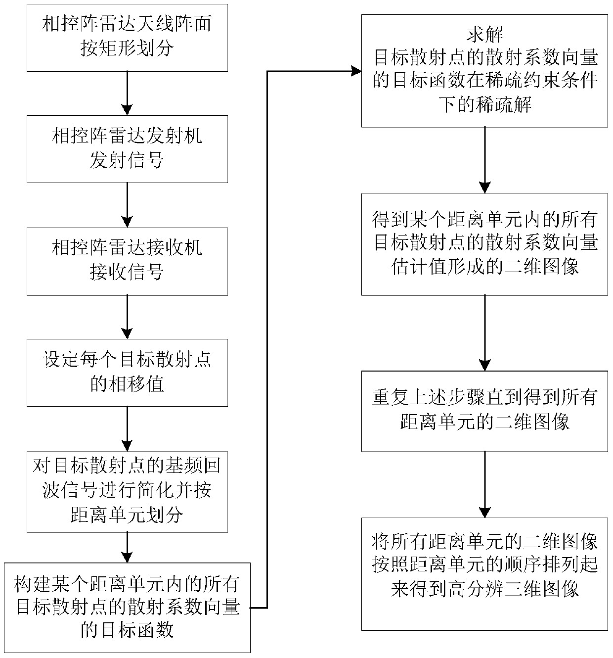
[0059] Referring to the present invention as figure 1 The shown scheme flow chart illustrates a three-dimensional associated imaging method based on phased array radar of the present invention. The specific implementation steps are as follows:

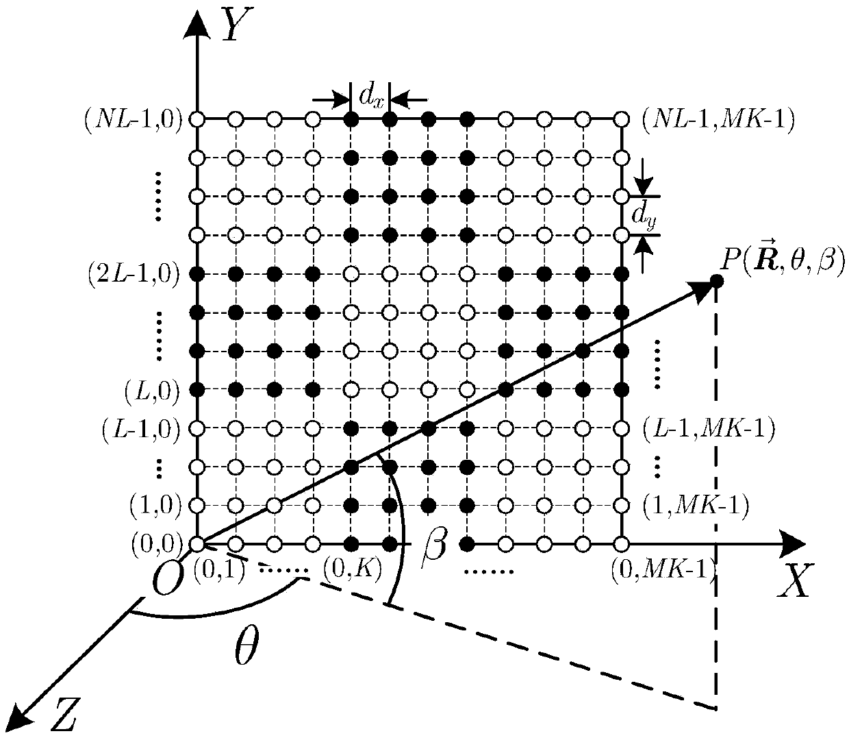
[0060] Step 1. Divide the phased array radar antenna array into M×N sub-arrays, each sub-array has K×L array elements, and there are a total of M×N×K×L array elements, and the array elements are uniformly distributed in a rectangle. The phased array radar transmitter transmits the chirp signal s0 at the qth pulse q Transmit into the imaging scene, and receive the echo signal containing P target scattering points under the qth pulse, which will be arranged in the k-th row and l-column of the sub-array of the m-th row and n-column of the phased array radar array The phase shift value of the array element at the pth target scattering point under the qth pulse is set as

[0061] 1a) As shown in Figure 3, the phased array radar antenna...


PUM


Abstract

The invention discloses a three-dimensional correlated imaging method based on phased array radar and relates to the field of radar imaging. The three-dimensional correlated imaging method based on the phased array radar comprises the steps that firstly, the antenna array surface of the phased array radar is divided, a linear frequency modulation signal is sent by a phased array radar transmitter, echo signals of target scattering points are received, and the phase shifting values of the target scattering points are set; secondly, base frequency echo signals obtained after distance pulse pressing are divided according to the distance unit; thirdly, an objective function for the scattering coefficient vectors of the target scattering points is constructed, and the objective function is solved under the sparse constraint condition, so that the estimated value of the scattering coefficient vector of the target scattering point in the u distance unit is obtained; fourthly, a two-dimensional image is formed through the estimated value of the scattering coefficient vector of the target scattering point in the u distance unit, and then a three-dimensional image is obtained by ranking the two-dimensional images of all the distance units in the sequence the same as that of the distance units. By the adoption of the three-dimensional correlated imaging method based on the phased array radar, high-resolution three-dimensional imaging of a target is achieved.

Description

technical field [0001] The invention belongs to the technical field of radar imaging, in particular to a three-dimensional correlation imaging method based on phased array radar. Background technique [0002] Microwave radar has the characteristics of all-weather, all-time, long-distance and large-scale observation. It can perform high-resolution imaging of target scenes and obtain detection information. It plays a key role in both civilian and military fields. As the main two-dimensional microwave imaging methods, synthetic aperture radar (SAR) imaging and inverse synthetic aperture radar (ISAR) imaging were rapidly developed in the 1950s, which use the relative motion between the carrier platform and the target to form a synthetic array manifold in space. , can obtain the scattering distribution information of the target in the range-Doppler plane, that is, the two-dimensional radar image, but the image has geometric distortion and lacks one-dimensional information, which ...

Claims


Application Information

Patent Timeline
Patent Type & Authority Applications(China)
IPC IPC(8): G01S13/90
CPCG01S13/90G01S13/9064G01S2013/0245
Inventor 李亚超许然邢孟道黄平平全英汇章浩波
Owner XIDIAN UNIV
Why Eureka
Try Eureka