Circuits for eliminating ghosting phenomena in display panel having light emitters

a technology of display panel and ghosting, which is applied in the direction of cathode-ray tube indicators, instruments, electric digital data processing, etc., can solve the problems of poor image quality, multi-dimensional driving, appearance of ghost effects and/or ghost images on display panels, etc., and achieve the effect of eliminating ghosting phenomena and eliminating ghost effects

Active Publication Date: 2012-08-16
SCT
View PDF5 Cites 18 Cited by
  • Summary
  • Abstract
  • Description
  • Claims
  • Application Information

AI Technical Summary

Benefits of technology

[0009]In another embodiment, there is provided a display panel. The display panel includes an array of light emitters having a common cathode, a power source electrically coupled to an anode of the light emitters, a selection circuit including a plurality of switches for sequentially selecting one or more of the light emitters, and a circuit for eliminating ghosting phenomena. The circuit for eliminating ghosting phenomena comprises a charge circuit for eliminating ghost images and a discharge circuit for eliminating ghost effects on the display panel, the discharge circuit comprising a ghost effect cancellation module electrically coupled to the anode of the light emitters, and the charge circuit comprising a ghost image cancellation module electrically coupled to the common cathode of the light emitters.

Problems solved by technology

One disadvantage of time-multiplexed driving, however, is the appearance of ghost effects and / or ghost images on the display panel.
This brief flash of light appears illuminated at improper times, resulting in poor image quality.
This usually leads to a large number of scan lines and switchable configurations that use the same current driver channel for a multiple of LEDs.
As a result, a large number of power switching elements and a large number of junction capacitances are required in such devices.
The stray capacitance becomes a nuisance in the design of the overall LED display system, because they retain small charges that create the ghosting phenomena.

Method used


Image

  • Circuits for eliminating ghosting phenomena in display panel having light emitters
  • Circuits for eliminating ghosting phenomena in display panel having light emitters
  • Circuits for eliminating ghosting phenomena in display panel having light emitters

Examples


Embodiment Construction

[0024]Reference will now be made in detail to embodiments of the present disclosure, examples of which are illustrated in the accompanying drawings. It is noted that wherever practicable, similar or like reference numbers may be used in the drawings and may indicate similar or like elements.

[0025]The drawings depict embodiments of the present disclosure for purposes of illustration only. One skilled in the art would readily recognize from the following description that alternative embodiments exist without departing from the general principles of the present disclosure.

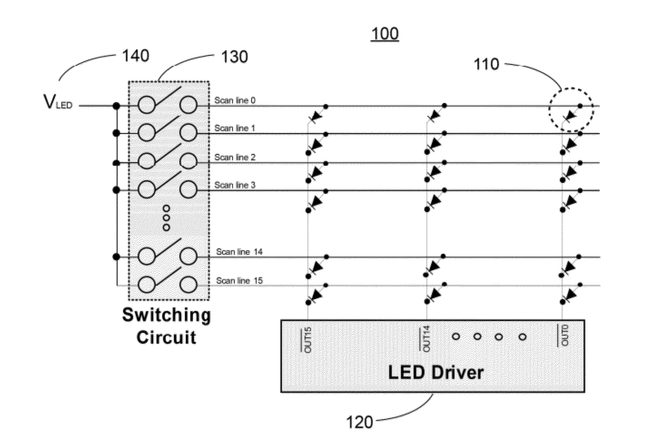
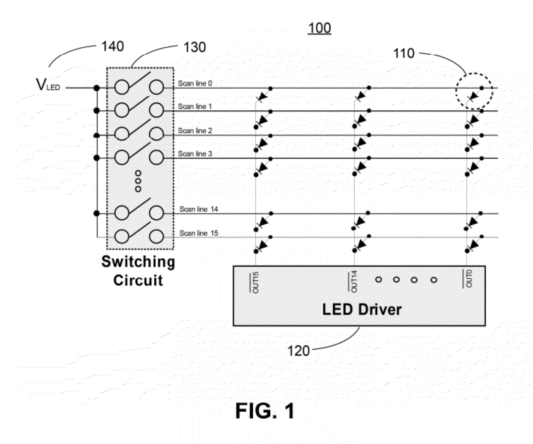
[0026]FIG. 1 illustrates an LED display panel 100 in accordance with one embodiment of the present disclosure. In this embodiment, LED display panel 100 is in a common anode configuration. In general, LED display panel 100 includes an LED current driver 120, an array of LEDs 110, and a switching circuit 130 to deliver power to LEDs 110 through a voltage source 140. In this embodiment, current driver 120 is coupled to ...


PUM


Abstract

The present disclosure provides a circuit for discharging parasitic capacitance in a display panel with common-anode topology having a plurality of light emitters, as well as a circuit for charging parasitic capacitance in a display panel with common-cathode topology. In the common-cathode topology, the circuit includes a three-terminal device having a gate, a source, and a drain, wherein one of the source and the drain is electrically coupled to a common cathode of the light emitters, and a mechanism for controlling the three-terminal device, the mechanism being electrically coupled to the gate. Shortly after a previously selected light emitter is unselected, the mechanism turns on the three-terminal device to form a conductive path between the source and the drain. The mechanism turns off the three-terminal device after a voltage at the common cathode is increased to a predetermined voltage level or after a maximum period of time lapses.

Description

RELATED APPLICATION[0001]This application claims the benefit of priority under 35 U.S.C. §119 to U.S. Provisional Application No. 61 / 443,703, filed on Feb. 16, 2011, the entire contents of which are incorporated herein by reference.TECHNICAL FIELD[0002]The present disclosure relates to a circuit for driving light emitters, such as light emitting diodes (LED). More particularly, the present disclosure relates to a circuit for driving an LED display including an array of light emitters, so as to reduce, cancel, or eliminate ghost effects and / or ghost images in the LED display.RELATED ART[0003]A display panel, such as an LED display, may be driven under time-multiplexed topology. One disadvantage of time-multiplexed driving, however, is the appearance of ghost effects and / or ghost images on the display panel.[0004]In general, a ghost effect refers to the trailing of a moving object appearing on a display panel. For LED displays, the ghosting phenomena may be caused by the stray board c...

Claims


Application Information

Patent Timeline
Patent Type & Authority Applications(United States)
IPC IPC(8): G09G5/00G09G3/32
CPCG09G3/32G09G2300/06G09G2330/04G09G2310/0275G09G2330/025G09G2310/0248
Inventor LI, ERICLU, CHUNXUE, JIANXINYANG, WENJIELI, WATTCHEN, YUTAOWEN, ZHIFENGCHIOU, SHEAN-YIHTANG, SHANG-KUANNADERSHASHI, NEDI
Owner SCT
Why Eureka
Try Eureka