Wind tunnel double light path schlieren flow field display apparatus

A display device, dual optical path technology, applied in measurement devices, instruments, aerodynamic tests, etc., can solve the problem of single optical path schlieren flow field image diffraction effect is obvious, schlieren background spots increase, and flow field pressure is low. and other problems, to achieve the effect of good flow field display effect, simple structure and low cost

Pending Publication Date: 2018-06-15
中国空气动力研究与发展中心超高速空气动力研究所
View PDF0 Cites 10 Cited by
  • Summary
  • Abstract
  • Description
  • Claims
  • Application Information

AI Technical Summary

Problems solved by technology

[0003] However, in the interval between the simulated height of more than 40 km and more than 50 km (the corresponding flow field static pressure is about 100Pa-20Pa, and the corresponding test Mach number is about M8-M12), when the conventional schlieren system is used, the flow field pressure is low ; When the glow discharge device is used, the flow field pressure is too high
At the same time, under the condition of hypersonic flow field, in order to improve the sensitivity of the single optical path schlieren display, the cutting amount of the knife edge is small, which will lead to the obvious diffraction effect of the single optical path schlieren flow field image and the increase of the schlieren background spots

Method used


Image

  • Wind tunnel double light path schlieren flow field display apparatus
  • Wind tunnel double light path schlieren flow field display apparatus
  • Wind tunnel double light path schlieren flow field display apparatus

Examples


Embodiment 1

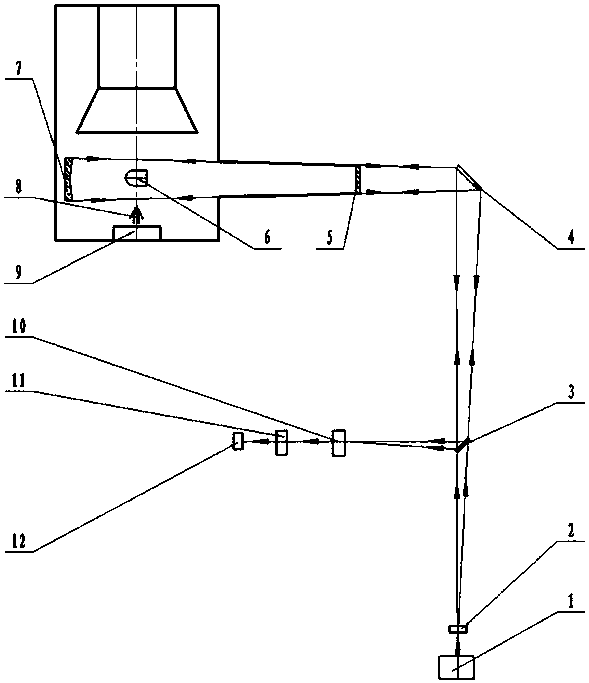
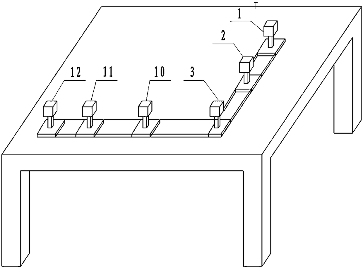
[0028] A dual optical path schlieren flow field display device in a wind tunnel, the device includes a fiber-coupled LED color light source 1, a condenser lens group 2, a beam splitter 3, a plane reflector 4, an optical window 5, a wind tunnel test model 6, and a spherical reflector Mirror 7, wind tunnel test section 9, knife edge 10, imaging objective lens 11 and camera 12;

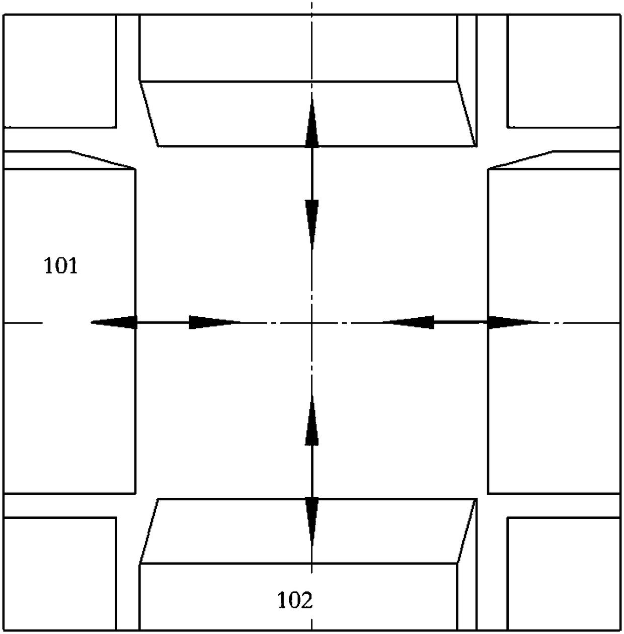
[0029] Such as figure 1 As shown, the wind tunnel test section 9 is a vacuum sealed cabin, and the test model 6 and the spherical reflector 7 are placed in the wind tunnel test section 9 in sequence;

[0030] Among them, fiber-coupled LED color light source 1, condenser lens group 2, beam splitter 3 and plane reflector 4 are placed in order, and planar reflector 4, optical window 5, wind tunnel test model 6, and spherical reflector 7 are placed in order Place the beam splitter 3, the knife edge 10, the imaging objective lens 11 and the camera 12 in order; the fiber-coupled LED color light source 1, the ...

Embodiment 2

[0052] Under the experimental conditions of Mach number Ma=10 and static pressure P∞=47Pa, the comparison results of the conventional schlieren flow field image and the double optical path schlieren flow field image of the large blunt test model are as follows Figure 4 and Figure 5 As shown, an ideal model flow field image is obtained. Figure 4 In the conventional schlieren image, the background noise spot A is very large, and the shock wave C of the large blunt test model cannot be displayed, and relatively serious diffraction fringes B are generated around the large blunt test model. Figure 5 The dual optical path schlieren diagram can clearly show the different airflow density regions D in the shock layer, and these flow field details are helpful for the diagnosis of the boundary layer flow field structure, and the obtained flow field image is clearer than the foreign test results .

[0053] The dual optical path schlieren optical system of the present invention has a...


PUM


Abstract

The invention belongs to the technical field of wind tunnel test apparatus, and specifically relates to a wind tunnel double light path schlieren flow field display apparatus. The wind tunnel double light path schlieren flow field display apparatus includes a fiber coupling LED color light source, a condenser set, a spectroscope, a planar mirror, an optical window, a wind tunnel test model, a spherical reflector, a wind tunnel test section, a cutter edge, an imaging object lens and a camera, wherein the wind tunnel test section is a vacuum sealed compartment; and the test model and the spherical reflector are successively arranged in the wind tunnel test section. The wind tunnel double light path schlieren flow field display apparatus has the advantages of being simple in structure, beinglow in cost, being preferable in the flow field display effect, and being convenient for operation. The wind tunnel double light path schlieren flow field display apparatus solves the flow field display problem which cannot be solved by a conventional schlieren and glow discharge apparatus for nearly continuous flow to rarefied transitional flow (the corresponding flow field static pressure is 100Pa-20Pa and the corresponding test Mach number is about M8-M12). The wind tunnel double light path schlieren flow field display apparatus also solves the problem which is not preferably solved for more than 40 years, that is, the double light path schlieren flow field display apparatus is easy to generate flow field image ghosting.

Description

technical field [0001] The invention belongs to the technical field of wind tunnel test devices, and in particular relates to a wind tunnel dual optical path schlieren flow field display device. Background technique [0002] In the ground test, although the flow field diagnostic technology has developed rapidly, so far there is no technology that can meet the needs of qualitative display and quantitative measurement of the hypersonic flow field when the simulated height changes from sea level to 100km. For the hypersonic flow field, when the simulated height increases from sea level to more than 40 km, the flow field density and static pressure of the flow field are relatively large (greater than 100Pa), and conventional schlieren is generally used (the light beam only passes through the test flow field One-time, sometimes called single-path schlieren) display technology, can obtain satisfactory flow field images. When the simulated height increases from more than 50 km to ...

Claims


Application Information

Patent Timeline
Patent Type & Authority Applications(China)
IPC IPC(8): G01M9/06
CPCG01M9/067
Inventor 李明石义雷祝智伟
Owner 中国空气动力研究与发展中心超高速空气动力研究所
Why Eureka
Try Eureka