

Backlight assembly, display device having the same and method of assembling the display device
- Summary
- Abstract
- Description
- Claims
- Application Information
AI Technical Summary
Benefits of technology
Problems solved by technology
Method used
Image

Examples
Embodiment Construction
[0036]Hereinafter, exemplary embodiments of the present invention will be explained in detail with reference to the accompanying drawings.
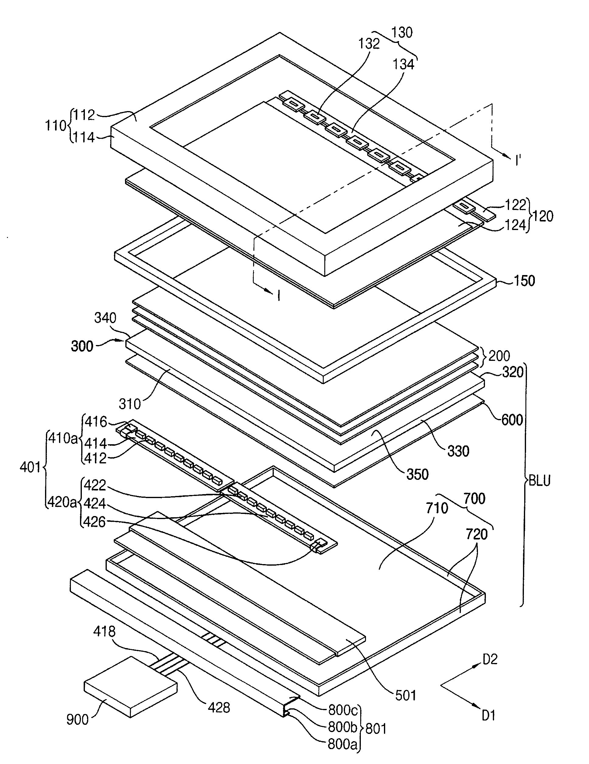
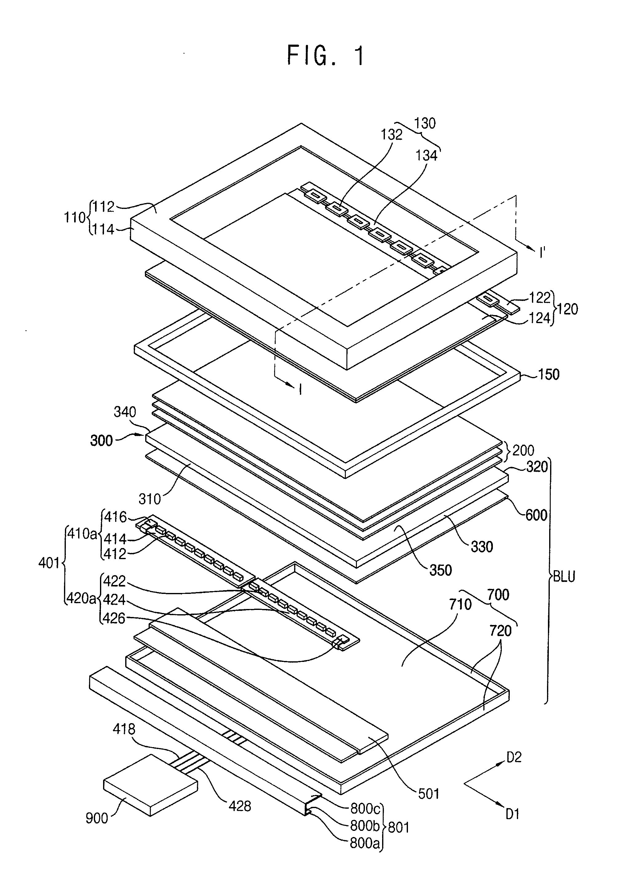
[0037]FIG. 1 is an exploded perspective view illustrating a display device according to an exemplary embodiment of the present invention. FIG. 2 is a cross-sectional view taken along a line I-I′ of FIG. 1.
[0038]Referring to FIGS. 1 and 2, a display device according the present exemplary embodiment includes a top chassis 110, a display panel 120, a panel driving part 130, a mold frame 150 and a backlight assembly BLU.
[0039]The top chassis 110 is disposed on the display panel 120 to protect the display panel 120 from an external impact. The top chassis 110 includes a panel supporting part 112 which supports edge portions of the panel 120 and plural chassis sidewalls 114 extended from the edge portions of the panel supporting part 112. A window exposing a display area of the display panel 120 is formed through an upper surface of the top chassis 110....
PUM
| Property | Measurement | Unit |
|---|---|---|
| Shape | aaaaa | aaaaa |
| Light | aaaaa | aaaaa |
Abstract
Description
Claims
Application Information