Power unit suspension structure for electric vehicle

a technology for electric vehicles and suspension structures, which is applied in the direction of electric propulsion mounting, jet propulsion mounting, transportation and packaging, etc., can solve the problems of power unit from the vehicle body breaking, the propagation of vibrations to the vehicle body cannot be efficiently reduced, and the load cannot be efficiently absorbed. , to achieve the effect of increasing the suspension rigidity preventing large oscillations of the power unit, and efficiently absorbing oscillations

Active Publication Date: 2012-08-23
SUZUKI MOTOR CORP
View PDF8 Cites 7 Cited by
  • Summary
  • Abstract
  • Description
  • Claims
  • Application Information

AI Technical Summary

Benefits of technology

[0025]Furthermore, in the present invention, the rear floor around the power unit includes the front portion, the rear portion higher than the front portion, and the slope portion provided between the front portion and rear portions and extending upward toward the rear part of the vehicle, and the front portion of the power unit is suspended from the front portion or the slope portion of the rear floor. Thus, the frame having substantially an L-shape in a side view of the vehicle and the stepped rear floor form a rectangular shape in a side view of the vehicle, thereby increasing suspension rigidity of the power unit.
[0026]In the present invention, the center of the power unit in the vehicle width direction on the vehicle front side of the power unit is suspended from the front portion of the frame at the same height position as the center of the shaft of the motor, and the vehicle rear side of the power unit is suspended via the longitudinal bracket from the vehicle body in the rear part of the vehicle with respect to the frame. This can efficiently absorb oscillation and a rotating load around the motor shaft generated during driving or deceleration of the motor. Also, only the vehicle rear side of the power unit is suspended from the vehicle body rather than the frame. Thus, the rigidity of the vehicle body can prevent large oscillations of the power unit, and when a load is applied to the vehicle from the rear, the load is applied to the vehicle body earlier than to the frame, thereby delaying a load on the power unit due to removal of the longitudinal bracket or the like.
[0027]As a result, the frame structure can be disposed with reference to the motor shaft of the power unit to determine the suspension positions. This allows the load to be received by each of the suspension portions, and achieves efficient load absorption.
[0028]Furthermore, in the present invention, the mounting bracket is provided in the vehicle body suspension portion on the vehicle rear side of the power unit, close to the connecting portion of the support member of the lateral rod near the crossing portion of the first reinforcing member extending in the vehicle width direction and the second reinforcing member extending in the vehicle front-back direction. This can increase rigidity of the vehicle body suspension portion, and provide the same advantage as the invention described above.
[0029]In the present invention, there are two or more vehicle body suspension points on the rear portion of the frame in the vehicle width direction with the center of the power unit therebetween, at least two of the vehicle body suspension points are offset in the vehicle front-back direction, the point on the side with the support member of the lateral rod is located in the rear part of the vehicle, and one, with the support member of the lateral rod, of left and right L-shaped vertical portions located near the inclined portion in the rear portion of the frame is disposed in the rear part of the vehicle. Thus, when the impact load is applied to the vehicle from the rear, the load is first applied to a portion on the side opposite to the high voltage terminal of the motor, thereby delaying movement of the high voltage terminal forward of the vehicle.
[0030]Therefore, according to the suspension structure of the present invention, contact between the high voltage terminal and a component in front of the high voltage terminal can be reduced to reduce breakage of the high voltage terminal.

Problems solved by technology

However, in the structure for suspending the power unit in the conventional electric vehicle described above, relative positions of the power unit, the frame, and the vehicle body, and a position of a suspension portion of the power unit from the vehicle body are not determined with sufficient consideration of loads generated in a vertical direction, a width direction, and a front-back direction of the vehicle when running, and a rotating load in the vertical direction of the vehicle due to torque variations of the motor during driving or deceleration.
Thus, the loads cannot be efficiently absorbed, and propagation of vibrations to the vehicle body cannot be reduced.
In conventional suspension structures, when a front impact load or a rear impact load is applied to the vehicle, and the load cannot be efficiently absorbed, a rubber bush in the suspension portion of the power unit from the vehicle body may break, or the power unit may be brought into contact with a structure in a front part of the vehicle.
Furthermore, in conventional suspension structures, when a lateral impact load is applied to the vehicle, a structure in a side part of the vehicle is easily brought into contact with the power unit, and a high voltage cable of the motor and a motor electrode terminal may break.

Method used


Image

  • Power unit suspension structure for electric vehicle
  • Power unit suspension structure for electric vehicle
  • Power unit suspension structure for electric vehicle

Examples


Embodiment Construction

[0036]Now, the present invention will be described in detail based on a shown embodiment.

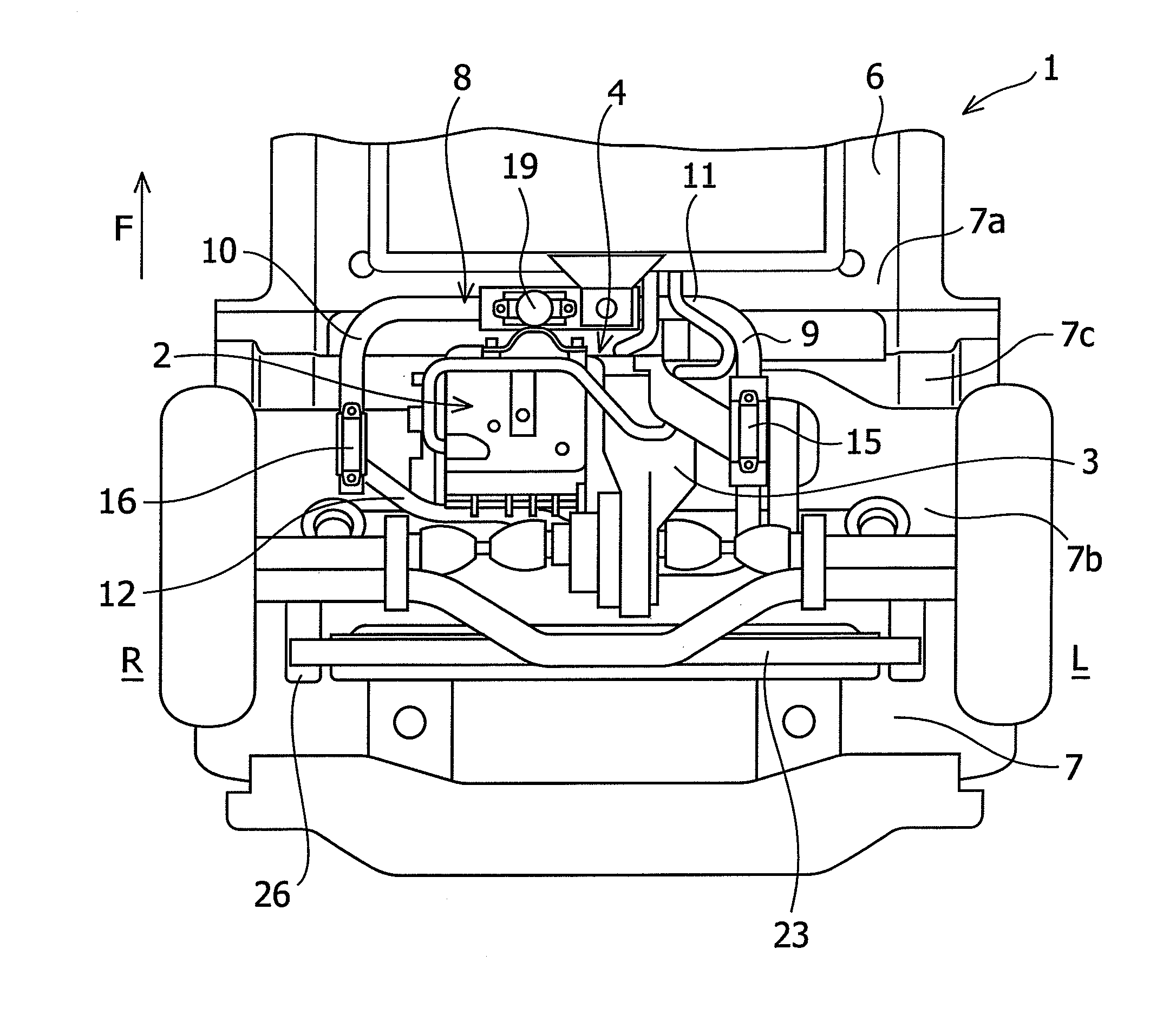
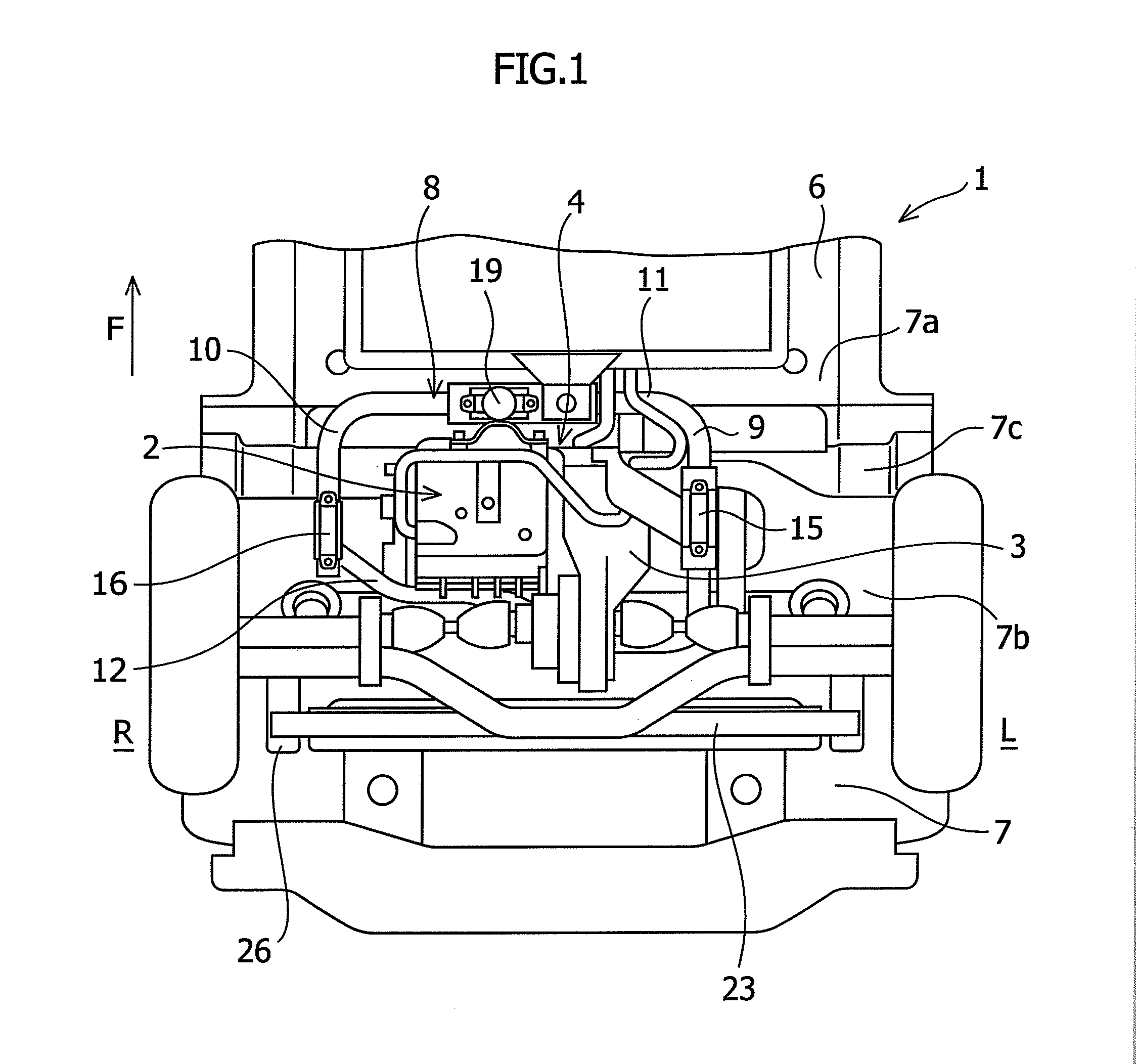
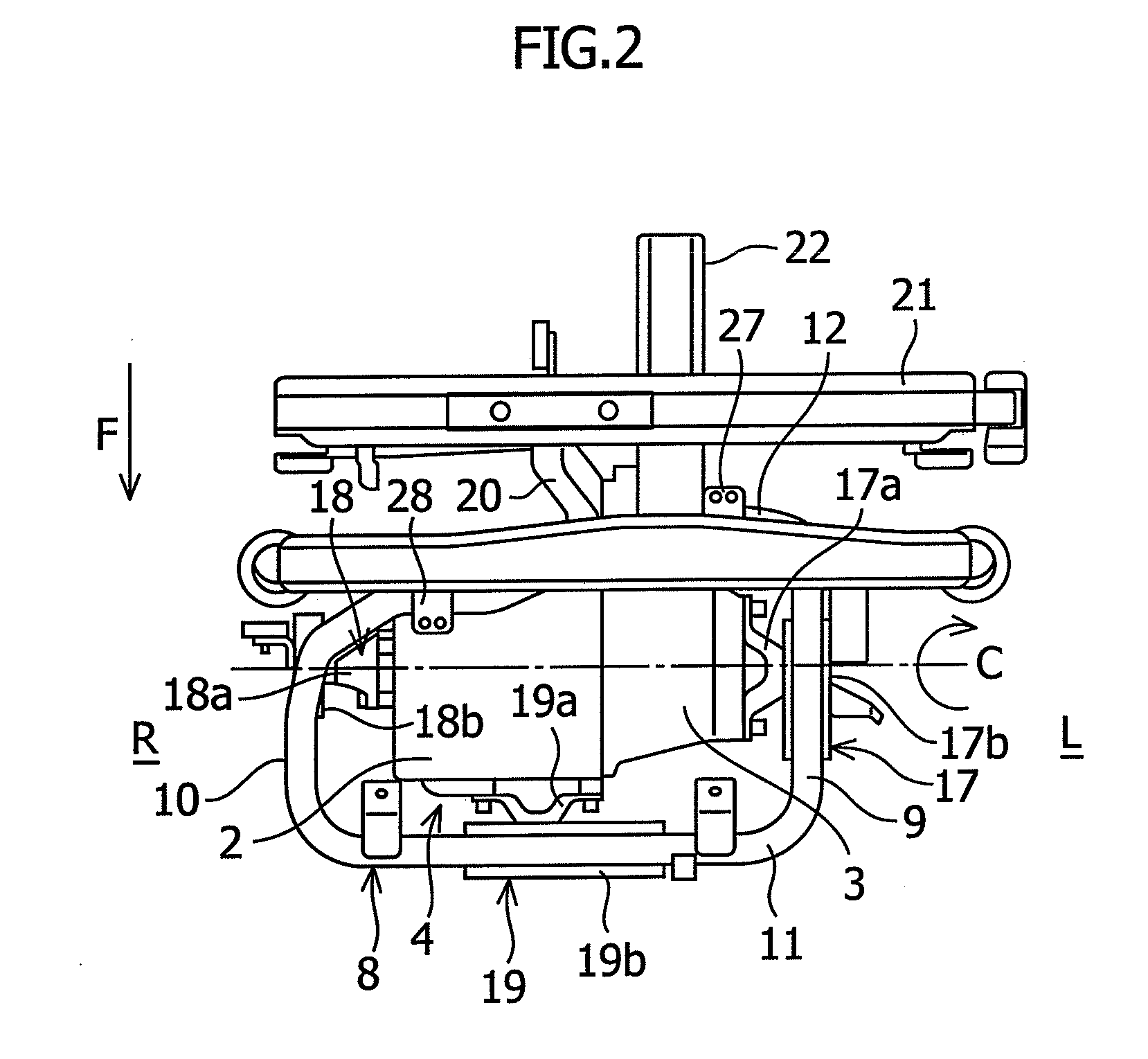
[0037]FIGS. 1 to 5 show a power unit suspension structure for an electric vehicle according to an embodiment of the present invention.

[0038]A vehicle to which the power unit suspension structure according to the embodiment of the present invention is applied is an electric vehicle 1. The electric vehicle 1 is a rear drive vehicle such as a commercial vehicle, and runs with a drive force of a motor (electric motor) to which power is supplied. As shown in FIGS. 1 to 5, a power unit 4 including a motor 2 and a motor speed reducer 3 is mounted in a rear part of the electric vehicle 1. A shaft C shared by the motor 2 and the motor speed reducer 3 is disposed in a vehicle width direction.

[0039]The power unit 4 is configured such that the motor speed reducer 3 is connected to a left side of the motor 2 in the vehicle width direction, and a longitudinal direction thereof is in the vehicle width directio...


PUM


Abstract

A power unit 4 is mounted in a rear part of a vehicle, a shaft C shared by a motor 2 and a motor speed reducer 3 is disposed in a vehicle width direction, and a sub-frame 8 is provided around the power unit 4, a front cross frame 11 is disposed over a front portion of the power unit 4 in a front view of the vehicle and disposed in parallel with the shaft C of the motor 2, a rear cross frame 12 is disposed over a side portion of the power unit 4 in a side view of the vehicle, and left and right side portions of the power unit 4 are suspended from a vehicle body via suspension brackets 13 and 14 provided on side frames 9 and 10, circular mount rubbers 15 and 16, and motor-side mount brackets 17 and 18.

Description

CROSS-REFERENCE TO RELATED APPLICATIONS[0001]The present application claims priority to Japanese Patent Application No. 2011-036898 filed Feb. 23, 2011.BACKGROUND OF THE INVENTION[0002]1. Field of the Invention[0003]The present invention relates to a suspension structure for a power unit mounted in a rear part of an electric vehicle.[0004]2. Description of Related Art[0005]In recent years, electric vehicles (EVs) that run with a drive force of a motor (electric motor) have been provided along with vehicles having a gasoline engine in consideration of the global environment. A power unit including the motor and a motor speed reducer is mounted in a rear part of the electric vehicle.[0006]Since such a power unit has a relatively large capacity and weight, a conventional electric vehicle includes a special structure with high rigidity in a lower part of a vehicle body, such as on a rear floor, to suspend the power unit (for example, see JP 4508260 B, JP 2008-222032 A, JP 2008-195259 A,...

Claims


Application Information

Patent Timeline
Patent Type & Authority Applications(United States)
IPC IPC(8): B60K1/00
CPCB60K1/00B60K2001/001B62D21/11B60K5/1216
Inventor TACHIBANA, YUICHINISHIKAWA, AKIHIROYAMANE, SHUICHIWAKATSUKI, SUNAO
Owner SUZUKI MOTOR CORP
Why Eureka
Try Eureka