
Battery cell arrangement

a battery cell and arrangement technology, applied in the field of battery cell arrangement, can solve the problems of affecting the service life of primary cells, and achieve the effect of reliable fixing of battery cells and cost-effective production

Active Publication Date: 2012-08-23
SAMSUNG SDI CO LTD
View PDF8 Cites 31 Cited by
  • Summary
  • Abstract
  • Description
  • Claims
  • Application Information

AI Technical Summary

Benefits of technology

[0005]One object of the present invention is therefore to provide a battery cell arrangement of the type mentioned initially, which is compact and allows reliable fixing of the battery cell. Another aim is for the battery cell arrangement to also comply with stringent safety requirements, and to be producible cost-effectively.

Problems solved by technology

For example, because of its pressure and / or its chemical reaction capability, the fluid can cause considerable damage to the components of the battery cell arrangement.

Method used


Image

  • Battery cell arrangement
  • Battery cell arrangement
  • Battery cell arrangement

Examples


Embodiment Construction

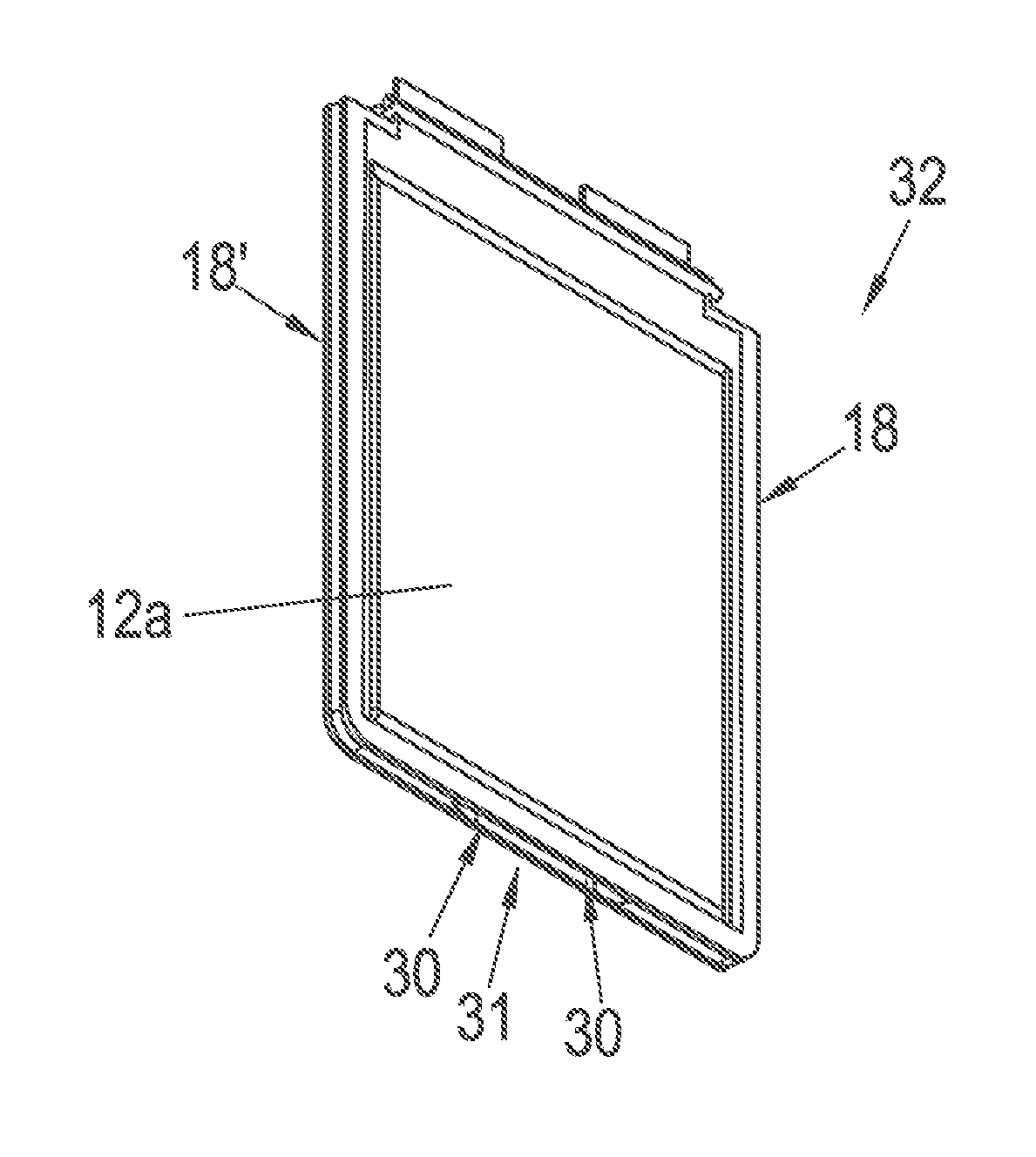
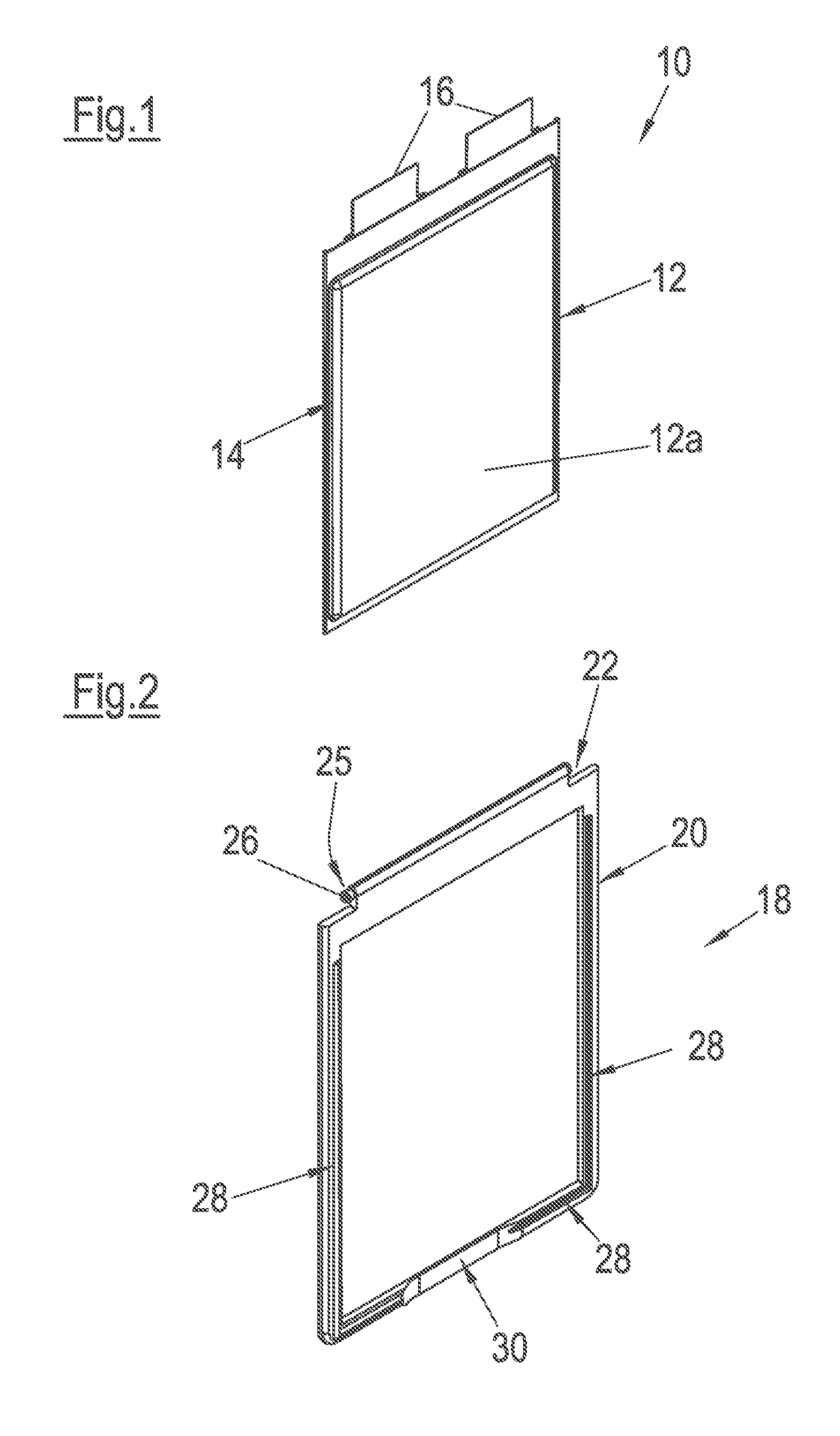
[0036]FIG. 1 illustrates a battery cell 10 which is in the form of a film cell. Film cells such as these are also referred to as pouch cells. .instead of a solid housing, they have a sheath in the form of a film, and therefore have a certain amount of flexibility.

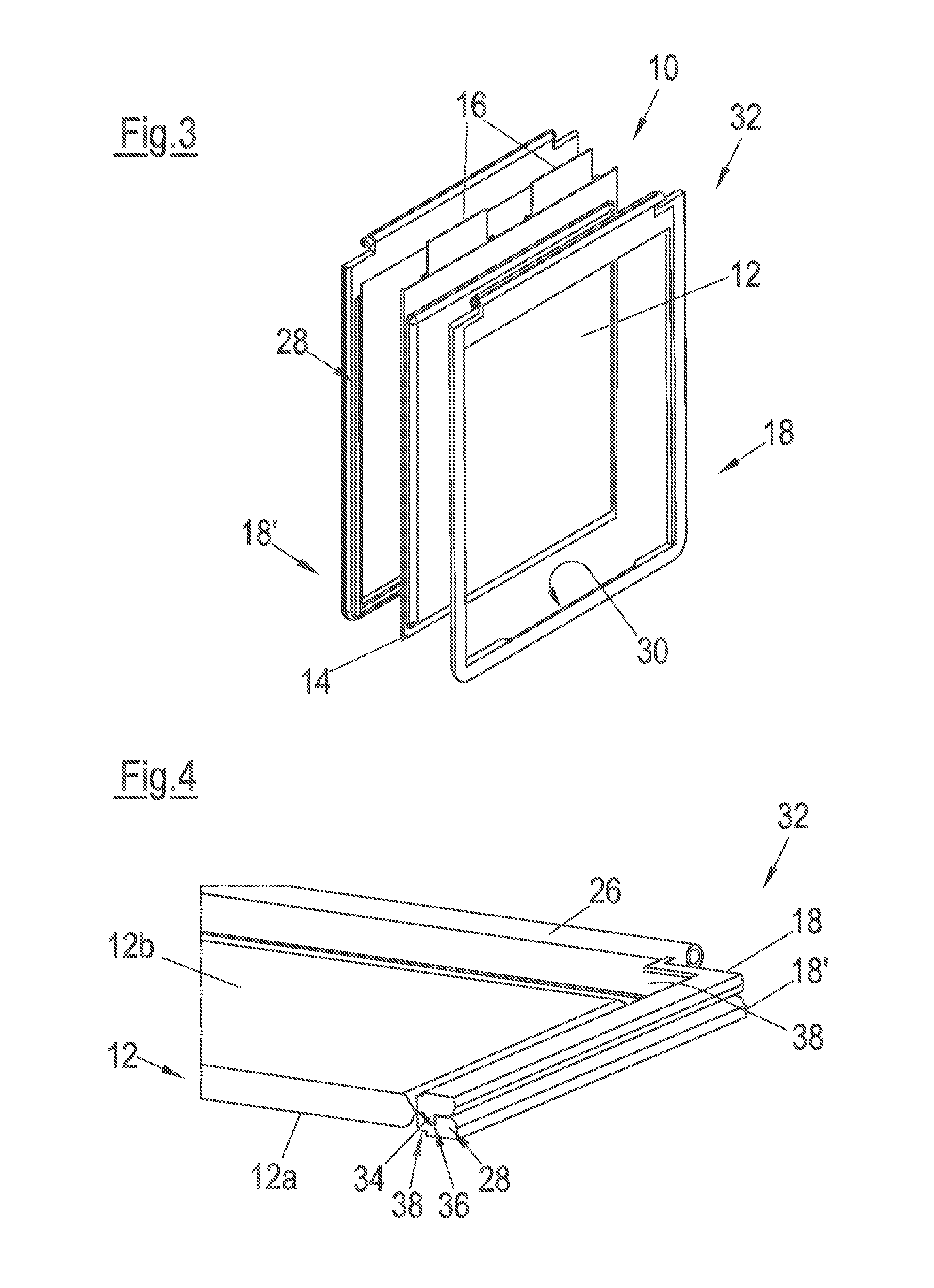
[0037]The battery cell 10 comprises a flat, rectangular cell body 12 with end surfaces 12a, 12b (end surface 12b cannot be seen in FIG. 1), which surrounds the functional components that are required to store electrical energy. On the outer perimeter thereof, the cell body 12 is surrounded by a cell rim 14 in the form of a fold. Furthermore, on the upper face (with respect to the vertical installation position illustrated here), the battery cell 10 has contact sections 16 by means of which the battery cell 10 can be electrically charged and / or discharged.

[0038]Since the battery cell 10 has comparatively little internal robustness, it must be provided with a supporting element, which is expediently of compact design. FIG. 2 ...


PUM


Abstract

A battery cell arrangement having a battery cell which is in the form of a film cell and includes a flat cell body with two end faces, a flexible cell rim surrounding the cell body, and two contact sections arranged on a rim side of the battery cell. The battery cell arrangement further has a frame arrangement which includes a first frame element and a second frame element which frames the cell body on all sides on the rim. At least one vent opening is provided on a side of the frame arrangement which faces away from the end faces of the cell body, in order to allow fluid, in particular gas, to emerge from the battery cell arrangement in the event of damage.

Description

CROSS-REFERENCE TO RELATED APPLICATIONS[0001]The present application is a National Stage Application of PCT International Application No. PCT / EP2010 / 066350 (filed on Oct. 28, 2010), under 35 USC. §371, which claims priority to U.S. Provisional Patent Application No. 61 / 255,640 (filed on Oct. 28. 2009), which are each hereby incorporated by reference in their respective entireties.FIELD OF THE INVENTION[0002]The present invention relates to a battery cell arrangement having a battery cell which is in the form of a film cell. BACKGROUND OF THE INVENTION[0003]Film cells such as battery cells do not have a solid housing, but the components of the battery cell which are required to store electrical energy are surrounded by a robust film which forms a cell rim, like a fold, on the narrow faces of the cell body. Because there is no solid housing, the battery cell has a certain amount of flexibility, making it easier to use in a physical space which is often confined. Furthermore, film cell...

Claims


Application Information

Patent Timeline
IPC IPC(8): H01M2/12H01M2/10H01M10/50H01M50/202H01M50/211H01M50/264H01M50/358H01M50/557
CPCH01M2/0212H01M10/5075H01M2/1061H01M2/1077H01M2/1235H01M2/1252H01M6/42H01M10/02H01M10/0413H01M10/0436H01M10/0486H01M10/5004H01M10/5016H01M10/5032H01M10/5057H01M2/0275H01M10/625H01M10/647H01M10/6556H01M10/6567H01M10/613Y02E60/10H01M50/557H01M50/342Y02P70/50H01M50/264H01M50/202H01M50/358H01M6/50H01M50/211H01M6/5038H01M10/65H01M10/60H01M10/6568
Inventor DAMON, PETERROEPKE, STEFANTHANNER, HERBERTWUNSCHE, RALPH
Owner SAMSUNG SDI CO LTD
Learn More