Method, system and device for uplink synchronization

a synchronization method and system technology, applied in the field of radio communication, can solve the problem of inability to perform uplink synchronization between an enodeb and a ue in the multi-carrier system

Active Publication Date: 2012-08-30
DATANG MOBILE COMM EQUIP CO LTD
View PDF4 Cites 112 Cited by
  • Summary
  • Abstract
  • Description
  • Claims
  • Application Information

AI Technical Summary

Benefits of technology

[0038]In the technical solutions according to the embodiments of the invention, an eNodeB selects one or more first component carriers which have not acquired uplink synchronization with the eNodeB from a plurality of component carriers supported by a user equipment and transmits a TA of the first component carrier to the user equipment, and the user equipment performs uplink transmission over the first component carrier according to the TA. Apparently the technical solutions according to the embodiments of the invention can establish uplink synchronization between the eNodeB and the UE in the multi-carrier system.

Problems solved by technology

An uplink synchronization establishment and maintenance method for an LTE-A multi-carrier system has been absent so far, thus making it impossible to perform uplink synchronization between an eNodeB and a UE in the multi-carrier system.

Method used


Image

  • Method, system and device for uplink synchronization
  • Method, system and device for uplink synchronization
  • Method, system and device for uplink synchronization

Examples


first embodiment

The First Embodiment

[0105]Assumed in this embodiment the system supports five UL CCs, which are indexed with CC1, CC2, CC3, CC4 and CC5 respectively. Taking the first situation in the first approach as an example, the UE with an initial access establishes synchronization of only one UL CC and will be extended to multi-carrier transmission. A specific flow is as follows.

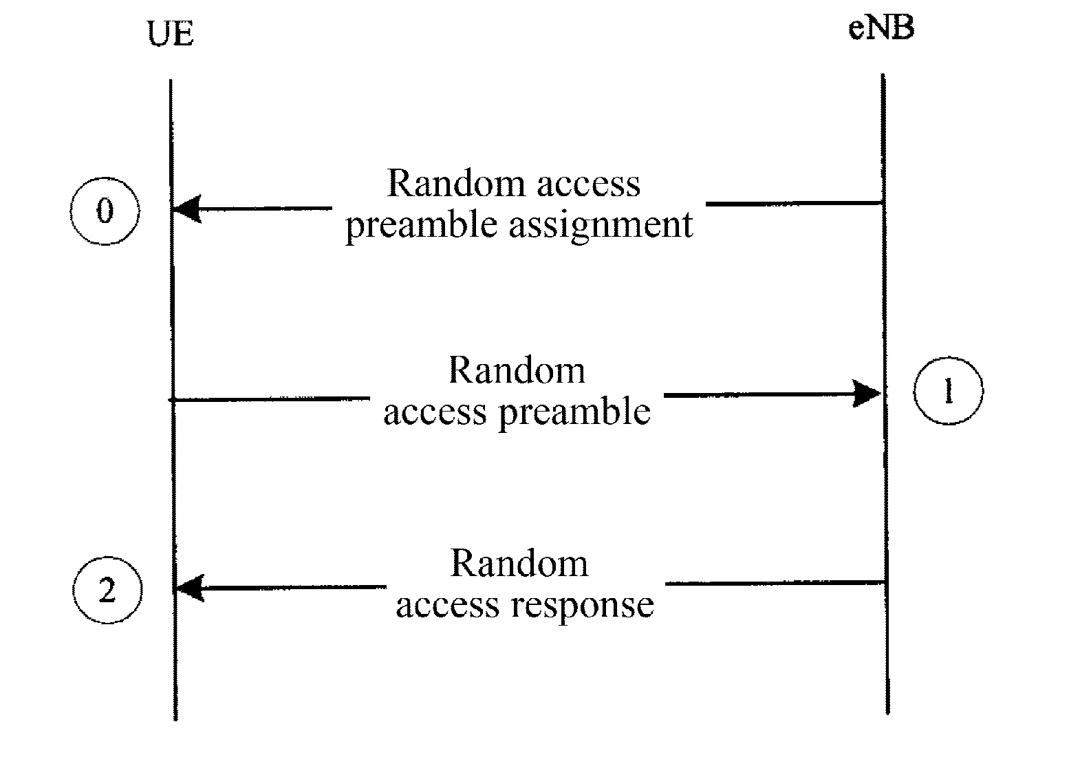
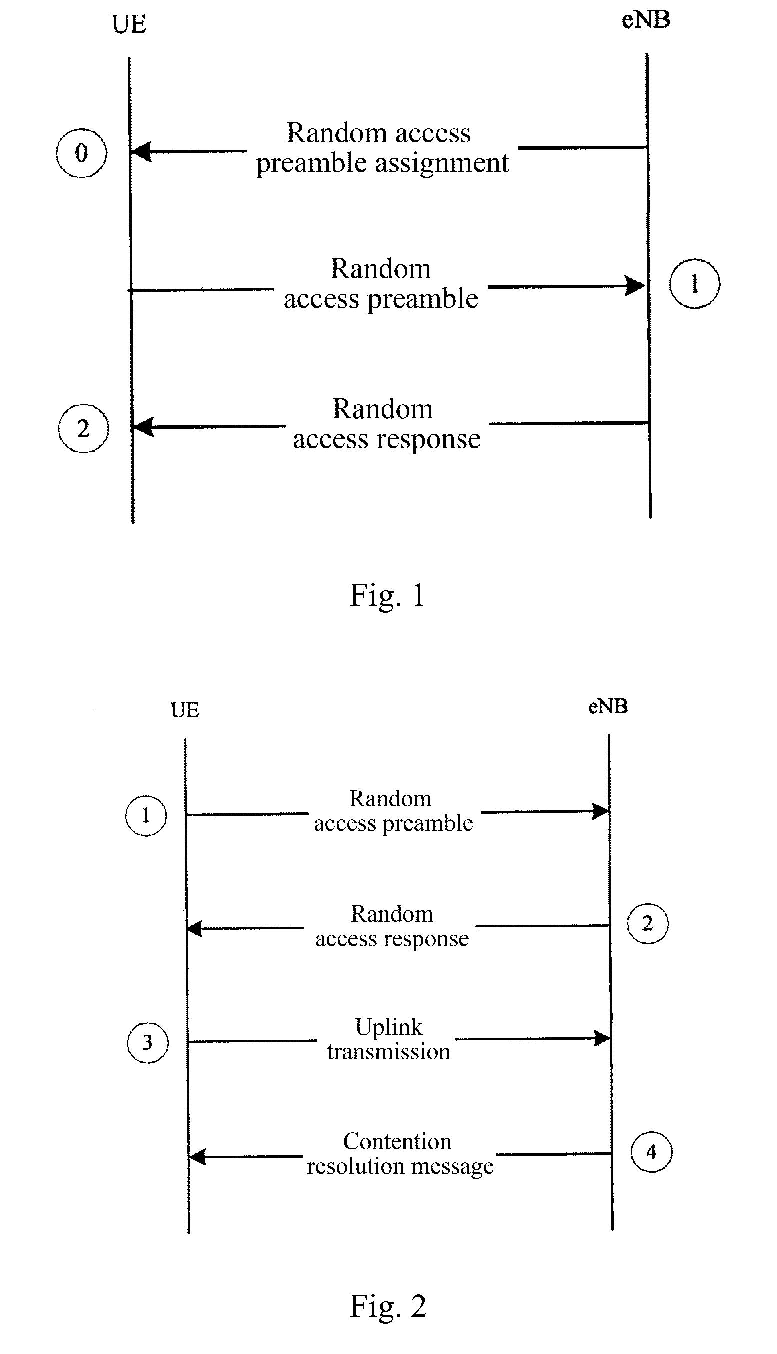
[0106]A step 01: The UE with a random access establishes uplink synchronization over the CC2.

[0107]A step 02: The eNodeB judges from uplink traffic of the UE that a Quality of Service (QoS) demand can be satisfied if three UL CCs are used for the UE to transmit data, for example, the CC1, the CC2 and the CC3, that is, the CC1 and the CC3 shall be newly added.

[0108]A step 03: The eNodeB transmits to the UE an RRC connection reconfiguration (RRCConnectionReconfiguration) message which includes a random access instruction message with the following contents:

[0109]if the UE is instructed to perform a non-contention random...

second embodiment

The Second Embodiment

[0120]Assumed in this embodiment the system supports five UL CCs, which are indexed with CC1, CC2, CC3, CC4 and CC5 respectively. For the fourth situation in the first approach, the number of carriers over which data is transmitted will be increased due to an increased amount of data for the same service of the UE. A specific flow is as follows.

[0121]A step 11: A set of available carriers initially configured for the QoS requested by the UE includes the CC1, the CC2 and the CC3. The amount of service data is small for a period of time, and then the UE deactivates the CC1 and the CC3 but transmits data over the CC2.

[0122]A step 12: The service fluctuates, and when there is burst data incoming, the eNodeB judges from a change to the amount of uplink service data that the QoS demand can be satisfied if three carriers are used for the UE to transmit the data and then activates the CC1 and the CC3.

[0123]A step 13: The eNodeB triggers a random access procedure over th...


PUM


Abstract

A method for uplink synchronization in a multi-carrier system includes the following steps: a base station selects one or more first component carriers, which do not establish the uplink synchronization with the base station, from multiple component carriers supported by a terminal; then the base station obtains Timing Advance (TA) needed by the terminal to perform the uplink transmission on the first component carriers, and sends the TA information to the terminal; the terminal performs the uplink transmission on said first component carriers according to said TA. The application of the present invention enables the establishment of uplink synchronization between the base station and the user equipment in multi-carrier system.

Description

[0001]This application claims priority to Chinese Patent Application No. 200910235660.7, filed with the China State Intellectual Property Office on Oct. 10, 2009 and entitled “Uplink synchronization method, system and device”, which is hereby incorporated by reference in its entirety.FIELD OF THE INVENTION[0002]The present invention relates to the field of radio communications and particularly to an uplink synchronization method, system and device.BACKGROUND OF THE INVENTION[0003]Significantly improved peak rates of 1 Gbps in the downlink and 500 Mbps in the uplink are required for a Long Term Evolution-Advanced (LTE-A) system as compared to a Long Term Evolution (LTE) system. Also good compatibility of the LTE-A system with the LTE system is required. Carrier Aggregation (CA) is introduced to the LTE-A system to accommodate the required improved peak rates, compatibility with the LTE system and full use of spectrum resources.[0004]Carrier aggregation refers to presence of a plurali...

Claims


Application Information

Patent Timeline
Patent Type & Authority Applications(United States)
IPC IPC(8): H04W56/00
CPCH04W56/0005H04W56/0045H04W56/00H04L7/0083H04L27/2657H04W92/10
Inventor ZHAO, YALIXU, FANGLIQIN, FEILI, GUOQING
Owner DATANG MOBILE COMM EQUIP CO LTD
Why Eureka
Try Eureka